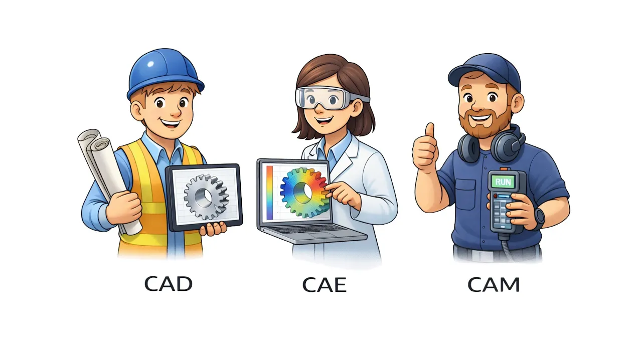

What Is CAM in Manufacturing? Process and Workflow
Learn More in This Video
Subscribe to GaugeHow for More
CAM in manufacturing is the software stage that takes finished CAD geometry, material and setup inputs, creates a machining strategy, and outputs CNC-ready instructions for mills, lathes, routers, and multi-axis machines. It turns a design model into a controlled production plan.
When CAM feels confusing, the problem is rarely the screen. Most of the confusion starts when design intent must be translated into a real machining plan.
That gap matters more now because the global CAM market was valued at $3.47 billion in 2023 and is projected to reach $6.20 billion by 2030 (Grand View Research, 2024).
On the shop floor, that means more connected digital workflows and less room for loose trial-and-error programming. At the same time, machinists and tool and die makers are still expected to see about 34,200 openings each year, on average, from 2024 to 2034 (BLS, 2025).
In practical terms, that raises the value of people who can release cleaner programs, shorten prove-out time, and catch mistakes before the machine moves.
If CAM still feels like a code generator, the wrong mental model is usually the reason. Strong CAM work is built around review, setup logic, tooling, cut strategy, simulation, posting, and first-part approval.
This blog provides a clearer structure. You will see what CAM really means, how it fits between CAD and CNC, what it controls, where failures begin, and what a release-ready program should look like.
What is Computer-Aided Manufacturing?
Computer-aided manufacturing is the software layer that turns design geometry into machining instructions. The model is one input, but it is not the only one. Material, stock size, machine limits, tooling, workholding, datum logic, and tolerance needs all shape the final program.
That is why CAM should be treated as a process, not just as software use. Here, the job is not drawing the part. The real job is deciding how the part will be made from real stock on a real machine with real limits.
That output is wider than many beginners expect. CAM creates toolpaths, operation order, spindle and feed settings, entry and exit behavior, stock allowance, and posted machine code. Once you see CAM in manufacturing as release logic rather than menu clicks, the topic becomes much easier to read.
How Does CAM Software Fit Between CAD and CNC?
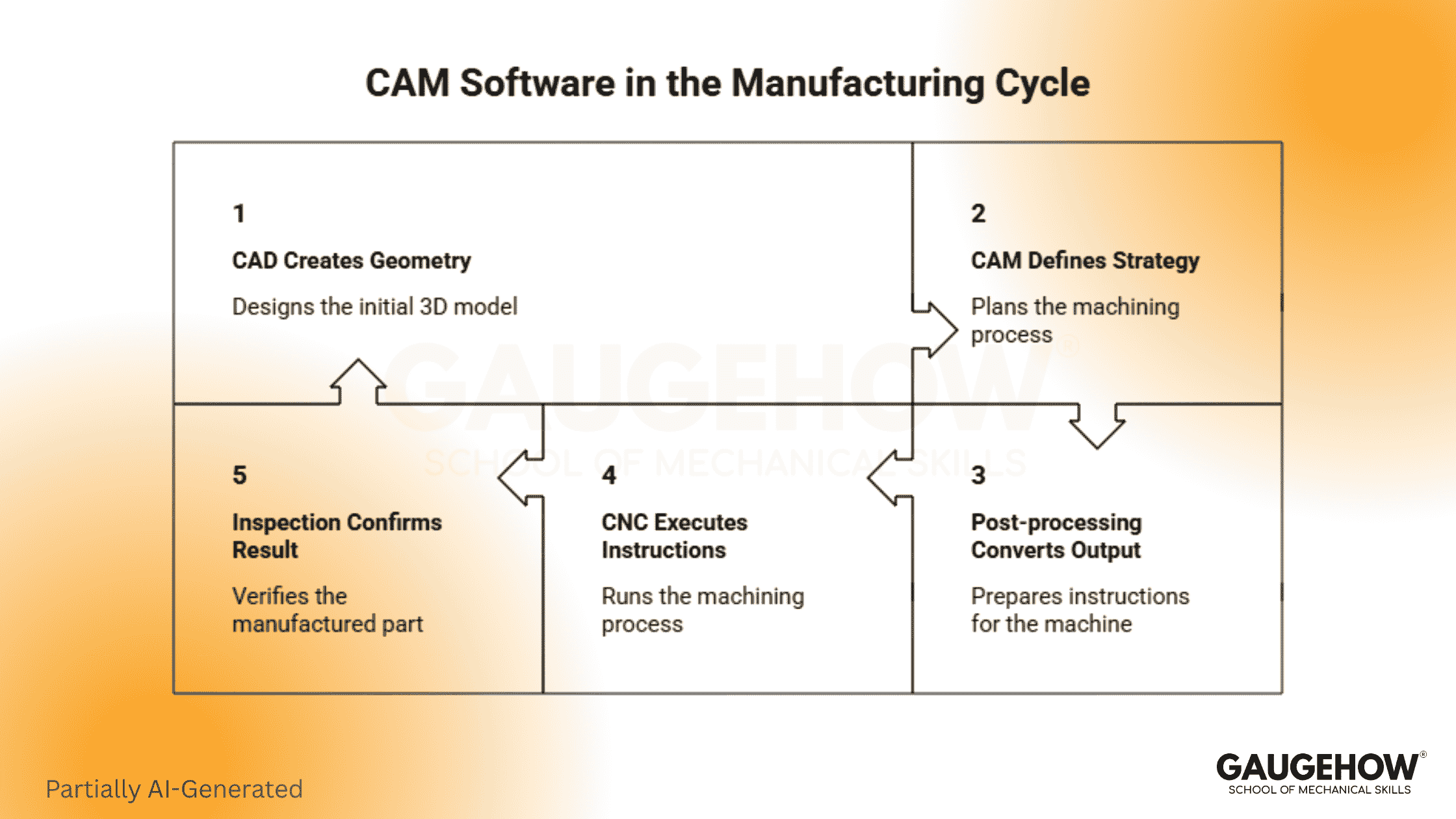
CAM software sits between geometry and machine execution. It is the planning layer that turns a finished model into a workable setup, a stable machining sequence, and controller-ready output.
Keep the chain simple:
● CAD creates the geometry.
● CAM defines the machining strategy.
● Post-processing converts the output.
● CNC executes the instructions. (Read More in CAM vs CNC)
● Inspection confirms the result.
That sequence is useful because it removes role confusion early. CAD answers what the part is. CAM answers how the part will be made. CNC answers how the machine will run that plan.
What Does CAM Actually Control?
The most useful answer is not “toolpaths.” That is too narrow.
CAM controls tool selection, which affects reach, rigidity, finish quality, and chip evacuation. A poor tool choice can make a seemingly safe program unstable within seconds.
It also controls motion strategy. Cut direction, engagement pattern, linking moves, re-entry behavior, and retract logic all shape cycle time and cutting stability.
Feeds, speeds, depth of cut, step-over, and stock allowance also sit inside CAM decisions. Those settings affect heat, tool life, finish quality, and dimensional repeatability. Operation order matters too because an awkward sequence can create vibration, distortion, or unnecessary rework later.
Posted output is the last control layer. A program that looks correct inside CAM can still fail if the post, controller logic, or machine assumptions are weak.
What Happens Between CAD Release and the first part?
Good CAM work follows a release sequence, not a random toolpath list.
You start with geometry review. The model must be complete, machinable, and clean enough for programming. Broken faces, bad imports, duplicate bodies, or messy edges slow everything down.
Next comes stock and setup planning. Raw material condition, fixture access, workholding direction, and datum logic shape the full process. Once those choices are locked in, tooling and operations planning become much more reliable.
Then roughing and finishing logic are built, cut conditions are set, simulation is run, output is posted, and prove-out is prepared. First-part inspection confirms whether the planned choices hold up on the machine.
Role/Task | Output | Tools | Downstream Use | Proof Check |
Geometry review | Clean programmable model | CAD viewer, repair tools | Stable start for programming | No broken or missing faces |
Stock and setup planning | Datum and workholding plan | CAM setup tools, fixture model | Safe access and repeatable location | Clear zero logic and clearance |
Tool selection | Tool and holder plan | Tool library, machine data | Reach, rigidity, finish control | Holder and engagement review |
Operation planning | Roughing and finishing sequence | CAM operations | Controlled material removal | Leftover stock and sequence check |
Parameter setting | Feeds, speeds, depth values | Operation settings, cut data | Stable cutting and cycle balance | Simulation and first-run behavior |
Post-processing | Controller-ready code | Post processor | CNC execution | Code and controller match |
First-part validation | Approved release state | Inspection tools, setup records | Repeatable production handoff | Critical feature confirmation |
Key Responsibilities in CAM Programming
A reliable CAM programmer owns more than path generation. The role is closely tied to quality, time, and release risk.
● Read the model and spot manufacturability issues early.
● Plan stock, datum, and setup logic clearly.
● Choose tools that match geometry and machine limits.
● Build roughing, semi-finishing, and finishing strategy.
● Set feeds, speeds, and cut values with judgment.
● Simulate honestly and review collisions, holders, and travel.
● Post the output for the correct controller.
● Support prove-out and first-part correction when needed.
Each responsibility ties to an output. Stronger planning leads to a cleaner setup, safer cutting, faster approvals, and less rework.
What Skills Make You Reliable in CAM Work?
Technical skill matters first, but reliable CAM work still depends on how you think under production pressure.
Hard Skills
Toolpath planning matters because it controls load, access, and sequence. GD&T reading matters because tolerance intent should guide process choices.
Understanding machine setup matters because a strong program still fails under weak workholding. Post-awareness matters because controller output must match the real machine, not the demo environment.
Soft Skills
Attention to detail matters because tiny mistakes can lead to costly consequences. Communication matters because setup teams, machinists, and inspectors need clear handoff logic.
Review discipline matters because most preventable failures can be caught before prove-out. Decision quality matters because CAM work involves trade-offs, not perfect options.
How the CAD to CNC Workflow Moves to the Machine
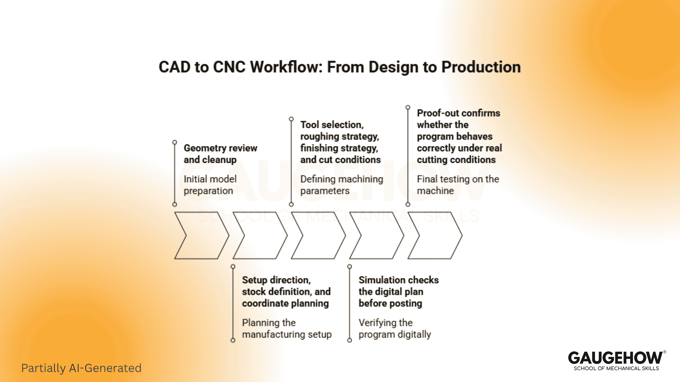
The CAD-to-CNC workflow starts with a released model, but the real movement begins when that model is tested against stock, setup, tooling, and machine limits. That is where programming turns design intent into production logic.
First comes geometry review and cleanup. After that, setup direction, stock definition, and coordinate planning take shape.
Tool selection, roughing strategy, finishing strategy, and cut conditions follow. Simulation checks the digital plan before posting, and converts it into controller output. Finally, a proof-out confirms whether the program behaves correctly under real cutting conditions.
Each stage protects the next one. Poor review weakens setup logic, which in turn destabilizes toolpaths, and unstable toolpaths create poor machine behavior. Good CAM work breaks that chain early and replaces it with controlled release steps.
Real CAM Examples That Teach Decision Logic
Pocketed Aluminum Bracket
The model may look simple, but the programmer still has to decide stock size, workholding direction, roughing approach, wall cleanup, and finish allowance. The output is a stable milling sequence. Success is confirmed when pocket size, flatness, and finish all hold on the first part.
Mold Cavity Surface
Surface quality matters as much as shape here. Tool choice, step-over, toolpath pattern, and rest-finishing logic determine whether the cavity comes off clean or requires heavy benchwork. Inspection and surface review confirm whether the strategy actually worked.
Turned Shaft With Shoulders
This job depends on sequence discipline. Facing, rough turning, shoulder control, groove order, and final passes all affect size, finish, and tool life. A clean result is confirmed through diameter checks, shoulder location, and repeatable output across parts.
Where the CNC Machining Process Usually Goes Wrong
A CNC machining process usually fails early when geometry, setup, tooling, or output assumptions stay unchecked. Most problems appear before the spindle ever starts cutting.
Geometry errors create wrong boundaries and unstable toolpaths. Setup errors can create incorrect zero points, block access, or cause weak clamping. Tooling errors show up as chatter, poor finish, taper issues, or broken tools. Parameter errors overload the cut or waste time without improving quality.
Simulation errors are just as serious because missing fixtures, weak holder data, or incomplete machine context create false confidence.
Posting errors can then turn a valid internal plan into bad controller output. Inspection gaps can cause damage to go undetected because a part may still appear acceptable even when missing a critical feature.
How Do You Choose CAM Software for Your Work?
Start with your work, not the interface.
If your parts change often and associativity matters, integrated tools usually make more sense. Revision handling becomes easier, and geometry updates flow faster into programming changes.
Mixed-file environments often push shops toward standalone options. Those systems can be stronger when machine coverage, specialist programming depth, or cross-platform import work matter more than design integration.
Post quality deserves close attention. So does simulation depth. Basic work can be reviewed more simply. Complex fixtures, expensive materials, and multi-axis motion usually require more rigorous verification. Training speed, template control, tool library quality, and machine support should also be judged before you commit.
What Should Be True Before You Post the Program?
This is the check many blogs miss, and it is one of the most useful habits you can build.
Before you post, confirm these points:
● Clean model
● Realistic setup
● Correct tools and holder stack
● Cut values that match the material and rigidity
● Simulation with the right stock and clearance logic
● A tested post for the exact controller
If any one of those points is weak, you do not really have a release-ready program. You only have a program running on-screen. A lot of wasted time starts right there.
Wrapping It Together
Treat CAM like production planning, not button clicking. That shift changes how you interpret the model, how you configure the setup, and how you evaluate the final output. Today, take one finished part model and walk it through the full release chain on paper before you ever touch the software.
FAQs
What is CAM in simple words?
CAM is the software step that takes a finished CAD model, adds machining decisions, and creates machine-ready instructions. It helps you move from part design to controlled cutting without having to guess each step on the machine.
Is CAM only for CNC programmers?
No. CAM matters to designers, programmers, machinists, and inspectors because it shapes tool choice, setup logic, sequence, and release quality. Anyone involved in part handoff benefits from understanding how that process is built.
What is the difference between CAM and G-code?
CAM is the planning system. G-code is the machine-ready output created after posting. One defines the machining logic, and the other translates that logic into the controller language the machine can run.
Why do CAM programs fail even after simulation?
Simulation only helps when the setup, fixtures, holders, stock, and machine assumptions are accurate. Weak input data creates false confidence, so the first real cut exposes problems that the screen never properly checked.
How should a beginner start learning CAM?
Start with part geometry, setup logic, tool basics, and simple toolpaths. Then learn how feeds, speeds, stock allowance, and simulation affect real cutting. That order builds judgment, which matters more than memorizing commands.
Mechanical Engineering Courses That Industry Actually Uses
Learn Tools of Design & CAD, Analysis & Simulation, Automation & Robotics, and Industry 4.0 used in modern factories.
Join 40+ Mech Courses like GD&T, Siemens NX, SolidWorks, CATIA V5, AutoCAD, ANSYS (FEA & Fluent), ABAQUS, Creo, Fusion 360, CNC Programming, Digital Twins, Python for Mechanical, and Industry 4.0.
Our Courses
Complete Course Library
Access to 40+ courses covering various fields like Design, Simulation, Quality, Manufacturing, Robotics, and more.


