
CAM Workflow: CAD Model to G-Code
Learn More in This Video
Subscribe to GaugeHow for More
A CAM process converts a finished CAD model into setup data, tool choices, cutter paths, simulation checks, posted code, and release-ready documents. Strong CNC programming starts long before code export because part intent, setup direction, and output quality shape every later approval.
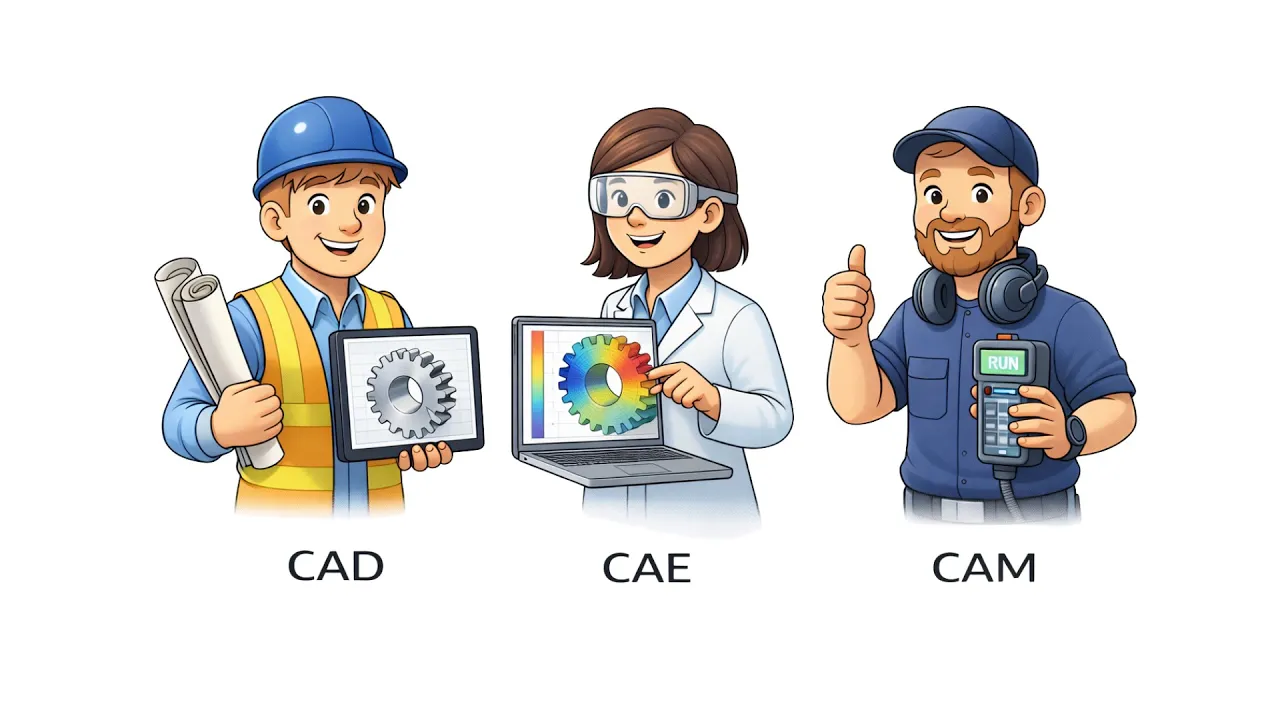
What CAM Software Does
CAM creates machining output from design geometry. Good output is not only code. Good output also includes sequence, setup direction, tool data, and review-ready release information.
A solid CAM process usually creates:
● Operation order
● Tool list
● Feeds and speeds
● Setup orientation
● Stock definition
● Cutter paths
● Posted code
● Setup sheet details
Each item changes the next decision. Tool choice changes cutter reach. Set up direction changes zero location. Stock definition changes roughing depth and linking moves. Posted code changes what the controller will actually read.
Strong CAM software helps build those outputs faster, but speed is not the main goal. Usable release quality is the main goal. Geometry alone does not tell the machine how to cut first, which face should become the base, or which tool should finish a wall. Engineering judgment still drives those choices.
Readable output also helps with review. Once sequence, tools, and setup are clear, approval becomes simpler, and revisions stay cleaner.
CAD to G-Code
CAD to G-code is a decision chain, not a one-click conversion. Geometry enters first. Manufacturing intent gets added next. Code comes out near the end.
Start with the model. Read the part as something that must be machined, checked, and released. Corner shape, tool access, wall stiffness, hole depth, and finish zones all influence the path plan.
Then define the setup. Base face, stock allowance, zero point, and clamp-safe zones shape the whole job. A weak setup plan creates avoidable edits because path logic now has to work around unclear part orientation.
A clean CAD to G-code process keeps three things aligned. Model intent must stay clear. Setup direction must stay practical. Output must stay reviewable. Lose one of those, and later sections get harder to trust.
Simple parts still benefit from this discipline. Complex parts need it even more because each added surface, tool, and setup raises approval effort.
Where CNC Programming Starts
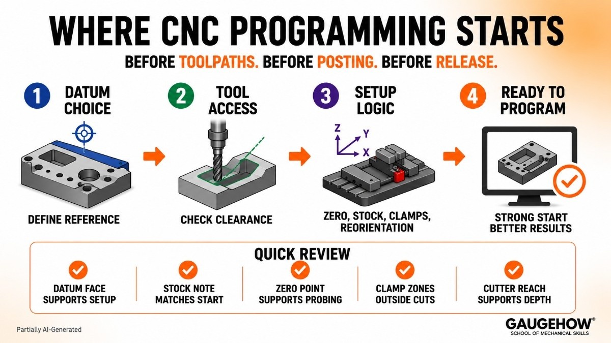
CNC programming starts when the part is read through machining intent. That moment comes before toolpaths, before posting, and before release.
Datum choice is the first major control point. Reference faces define how setup logic will be read later. A weak datum choice shifts zero logic, confuses setup notes, and slows approval because every later output now rests on a softer base.
Tool access comes next. Pocket width, corner radius, holder clearance, and stickout all shape which cutter can enter the feature cleanly. Small access changes often alter finish strategy, path direction, and final cycle structure.
Setup logic also deserves more attention than most pages give it. Zero location affects every move. Stock size affects roughing depth. Clamp position affects entry moves. Reorientation between setups affects release notes and part handling.
Use this quick review before deeper CAM work:
● Datum face supports setup logic
● Stock note matches real start state
● Zero point supports clear probing
● Clamp zones stay outside cut regions
● Cutter reach supports feature depth
That review prevents vague output later. Better CNC programming always starts with stronger setup thinking.
Toolpath Generation
Toolpath generation turns setup intent into cutter motion. Roughing removes bulk material. Semi-finishing controls remaining allowance. Finishing shapes final walls, floors, and blends. Drilling and contour passes then follow the part needs.
Path quality depends on more than path shape. Tool diameter, stepdown, stepover, entry moves, retract style, and linking behavior all change output. A path may look complete on screen and still waste time through long air moves or poor cutter engagement.
Use toolpaths to create clear deliverables, not just visible motion. Good paths should show a sensible order, stable cutter use, and a finish plan that another reviewer can understand quickly.
A second pass on toolpath generation often improves the result more than adding extra operations. Shorter links reduce dead motion. Cleaner rest passes protect finish zones. Smarter stepdown choices improve surface control and tool life together.
Path strategy should answer one question at every stage: what gets created here, what changes next, and what can now be approved?
Simulation and Validation
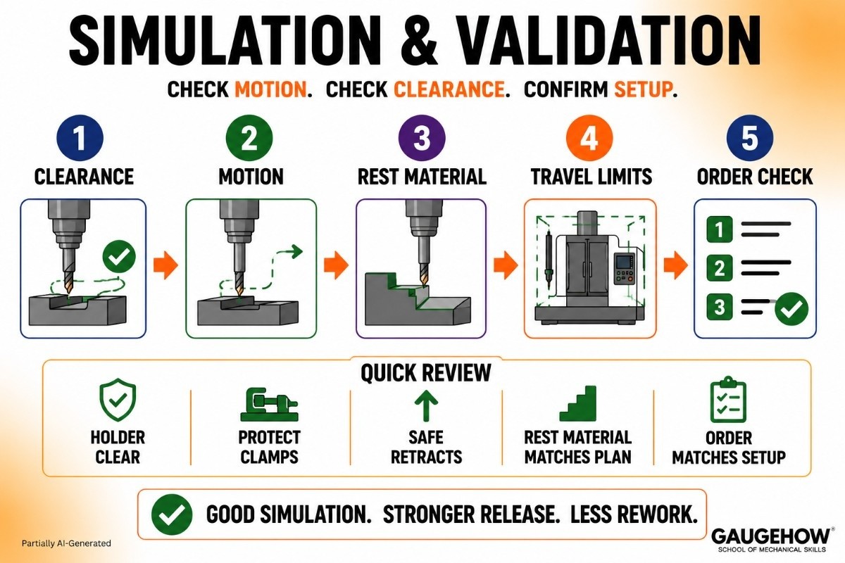
Simulation and validation check whether planned motion still holds up under real machine conditions. Visual motion alone is not enough. Clearance, travel, and setup alignment all need a review.
Start with holder clearance. Then check approach moves, rest material, retract height, and depth sequence. Travel limits deserve attention as well because long tools and deep features can push the program close to machine constraints.
Run simulation and validation with purpose. Look for a mismatch between intended setup and actual motion. Watch entry behavior around clamps. Review how the tool exits narrow areas. Confirm that the operation order still suits the part condition at each stage.
Use this review block in the hardest jobs:
● The holder stays clear through depth
● Entry moves protect clamp zones
● Retracts suit part height changes
● Rest material matches next pass plan
● Final cut order matches setup note
Strong simulation shortens review time because it turns hidden doubts into visible checks. Clean motion on screen does not guarantee clean release, but it does remove a large share of preventable rework.
Post Processing in CAM
Post-processing in CAM converts generic path data into controller-specific output. Until that stage finishes, the machine still does not have usable code.
A post-processor changes more than file format. It shapes tool call style, canned cycle style, work offset output, safe start blocks, arc behavior, and controller dialect. Two different posts can produce two very different outputs from the same path logic.
That is why the post choice should be treated as a decision section, not a glossary section. Posted output must match machine expectations, setup notes, and controller habits. Otherwise, path quality alone cannot save the program.
Read the first posted blocks carefully. Opening lines reveal whether the post is producing stable output. Tool calls, spindle lines, offsets, and safety lines should match the approved plan. Mid-program lines should also show clear transitions between operations.
Strong post-processing in CAM creates readable code, not just machine-readable code. Readable output supports cleaner review, smoother edits, and safer release.
Machine-Ready G-Code
Machine-ready G-code is posted output that can move into approval without guesswork. That means code, setup notes, and operation intent all tell the same story.
A good first read should confirm basic alignment. Opening blocks should match the tool list and offset plan. Depth moves should match the operation sequence. End blocks should leave the machine in a clear state.
One more pass over the machine-ready G-code should focus on transitions. Tool changes, coolant calls, feed shifts, and cycle calls should appear where the setup sheet expects them. Review becomes much easier when every code block supports a known operation.
Code quality is not only a machine issue. Code quality is also a communication issue. Reviewers need to understand what will happen, in what order, and under what setup condition. Clear output reduces back-and-forth during release because fewer hidden assumptions remain in the file.
Release Truth Check
Most competitor pages stop too early. Release quality needs one more layer. Model revision, setup notes, tool data, and posted output must stay aligned.
Use Release Truth Check before final approval:
● Model revision matches setup sheet
● Tool numbers match the posted file
● Work offset call matches setup plan
● Stock note matches the operation start
● Output file name matches revision
A second post-processor check belongs here, too. Confirm that the posted file still reflects the approved machine and controller choice. Small post changes can alter safe start lines, cycle style, or arc behavior without changing the visible path on screen.
Release clarity has job-level value. Accurate labels reduce confusion. Clean notes shorten review loops. Strong alignment supports smoother handoff between programming, setup, review, and release.
Most Asked Questions
What is CAM workflow?
CAM workflow is the sequence that turns a CAD model into setup data, toolpaths, posted code, and release documents. Good structure keeps model intent, setup direction, and final output aligned from first review to approval.
What does CAM software output?
CAM software outputs machining sequence, tool data, feeds and speeds, stock setup, cutter paths, and posted code. Better output also supports setup sheets and review notes, so release work stays cleaner and faster.
Is CNC programming only code writing?
No. Code writing is only one part. Real programming also includes datum logic, stock direction, tool choice, cut order, path structure, simulation review, and final release checks before approval.
Why is toolpath generation important?
Toolpath generation controls cut order, engagement, finish approach, and dead motion. Strong path planning improves readability, reduces avoidable edits, and helps reviewers understand exactly how the part will be machined.
What does a post-processor do?
A post-processor converts generic CAM path data into machine-specific output. It changes file structure, cycle style, offsets, tool calls, and other controller-facing details needed for stable final code.
Mechanical Engineering Courses That Industry Actually Uses
Learn Tools of Design & CAD, Analysis & Simulation, Automation & Robotics, and Industry 4.0 used in modern factories.
Join 40+ Mech Courses like GD&T, Siemens NX, SolidWorks, CATIA V5, AutoCAD, ANSYS (FEA & Fluent), ABAQUS, Creo, Fusion 360, CNC Programming, Digital Twins, Python for Mechanical, and Industry 4.0.
Our Courses
Complete Course Library
Access to 40+ courses covering various fields like Design, Simulation, Quality, Manufacturing, Robotics, and more.


