
CNC Programming: CAM, G-Code, and Machine Logic
Learn More in This Video
Subscribe to GaugeHow for More
CNC programming converts part geometry and machining intent into executable machine instructions. CAM sits inside that process by building a toolpath from model data, tool selection, cutting order, and machining strategy. G-code then carries that toolpath as an output language that a controller can read block by block.
Machine logic is controller behavior during execution, including active mode, work offset, spindle state, interpolation, and machine response.
Each layer controls the next one, so code quality depends on engineering judgment long before a cutter enters material.
Programming, therefore,e starts upstream, not at the control. Geometry has to be interpreted first. The sequence has to be structured next.
The setup reference has to be chosen with care. Only after those decisions are stable does a code file become useful, because machine behavior is always the result of prior planning.
What Is CNC Programming?
CNC programming is the process of defining how a machine should make a part. Motion, sequence, coordinate logic, spindle behavior, tool calls, and control functions are arranged into an execution logic that the controller can follow without ambiguity.
A coherent program changes machining quality immediately. Feature order becomes deliberate, so toolpath flow stays cleaner. The setup reference becomes explicit, so positional behavior stays more stable.
Machine response becomes easier to predict, so validation takes less guesswork and less rework.
Another point belongs early. Programming is not only line writing.
Programming is the act of converting geometric intent into controlled machine behavior, which is why planning skill and code skill always sit together.
What Is G-Code?
G-code is the most common output language used to communicate programmed motion and machine actions to a CNC controller.
Program blocks describe position, interpolation, feed behavior, plane selection, spindle action, and related control functions, so the machine can execute a defined sequence rather than a manual interpretation.
Every block creates a direct outcome. A position command changes location, so feature placement changes with it. A feed value changes cutting behavior, so load, finish, and cycle time change with it.
A spindle command changes the machine state, so the next move may become valid or invalid depending on the order.
Fluent code reading grows from that cause-and-effect view. Syntax alone does not create confidence. Execution logic does.
What Are the Main Programming Methods?
Most CNC work is built through three methods. CAM programming generates toolpaths from geometry and machining strategy. Direct G-code programming writes or edits program blocks directly.
Conversational programming generates standard features through guided prompts inside software or controller interfaces.
Method choice affects efficiency because each path fits a different job. Simple parts often respond well to direct code or conversational routines, since setup logic stays visible and overhead stays low.
Complex geometry usually benefits from CAM, since toolpath generation, linking motion, and post-processing are already structured around the model.
Hybrid workflows are common for the same reason. CAM may generate the main sequence. A direct edit may refine a short region. Conversational logic may handle a standard pattern quickly. Productivity rises when method follows part logic rather than habit.
How Do G-Code Dialects Differ?
G-code is common across CNC, yet controller dialects still vary in supported cycles, formatting rules, parameter behavior, defaults, and syntax details.
A program that looks clean in general form may still need revision for another control, because execution logic is filtered through the target controller’s dialect. (cnccookbook.com)
Dialect differences affect machining through interpretation. One control may accept a compact format. Another may require a stricter structure. One platform may support a cycle directly.
Another may need a different block sequence. Once those differences are ignored, machine response can drift even when geometry and toolpath intent are correct.
A post-processor handles that translation layer. CAM builds an internal toolpath first. Post logic then converts it into controller-specific output. Translation quality, therefore, has a direct effect on execution quality because syntax, command mapping, and control expectations are resolved there.
How Do CNC Coordinates Work?
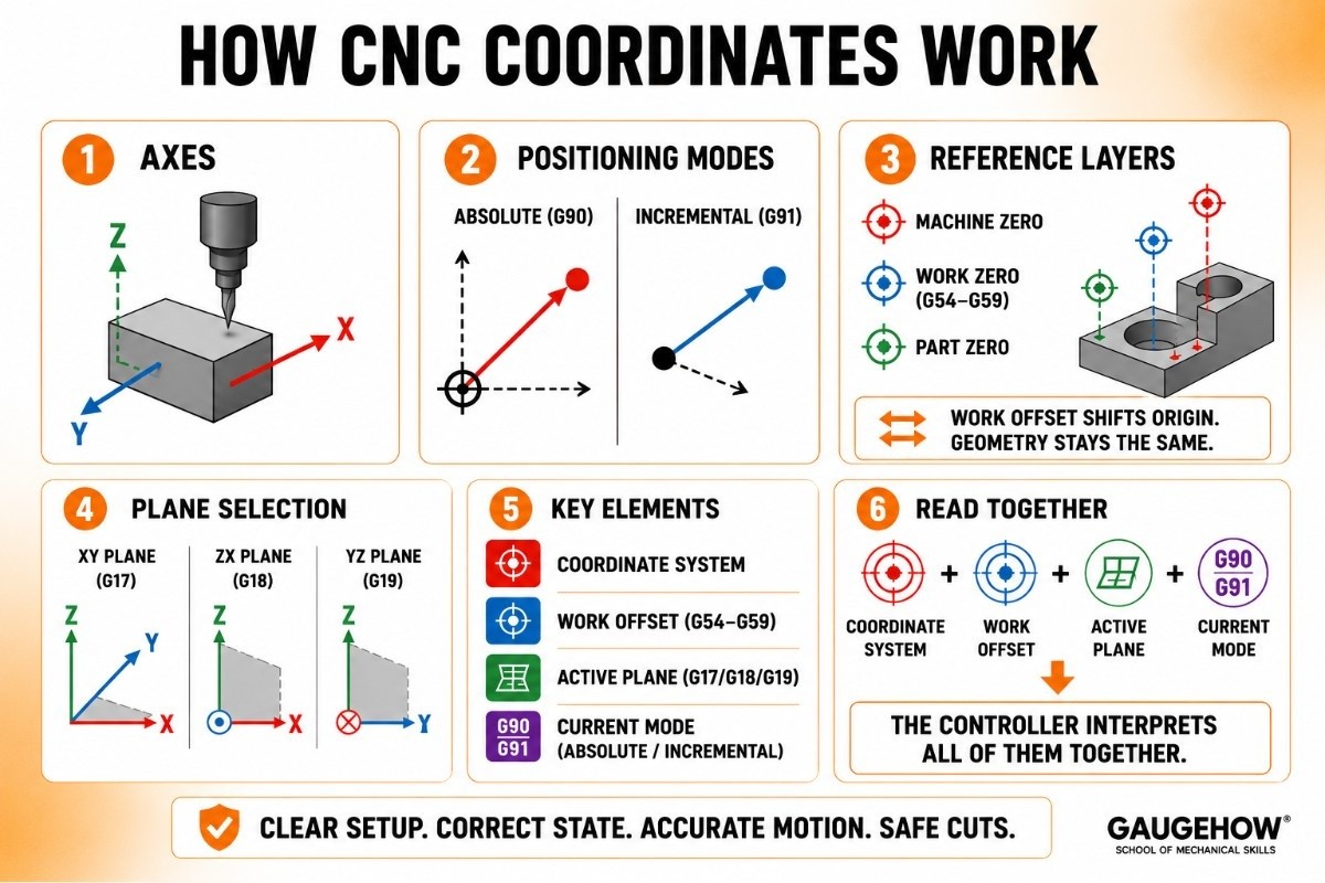
Coordinate systems define how a controller interprets programmed motion in space. Linear axes such as X, Y, and Z establish location. Rotational axes extend motion on more advanced machines.
Since every cut depends on position, coordinate logic is part of core execution logic rather than background theory.
Absolute positioning ties motion to an active origin, so feature location stays anchored to one setup reference. Incremental positioning ties motion to the current point, so local geometry can be expressed more compactly.
Program blocks read very differently depending on which mode is active, sso he coordinate state always needs to be read before motion meaning is assumed.
Reference layers deserve equal attention. Machine zero belongs to the machine structure. Work zero belongs to the setup reference. Part zero belongs to geometric intent.
A work offset shifts program origin without rewriting core geometry, so one file can support different fixture locations or repeated part positions.
Coordinate confidence rises once those layers are kept separate, because the controller always acts through active reference rather than through drawing intent alone.
Plane selection adds another layer. Interpolation depends on the active plane, so arc behavior is controlled by more than endpoint values.
Coordinate system, work offset, active plane, and current mode should therefore be read together, because the machine interprets all of them together.
What Software Helps Most?
Software helps most when it removes the current bottleneck without hiding process logic. CAM reduces path-building effort, so geometry-heavy work can move forward faster.
A G-code editor reduces inspection and revision effort, so program blocks become easier to clean, reorder, and compare. A simulator or backplotter reduces uncertainty, so the machine response can be checked before execution.
Each category represents a different stage of work. CAM improves toolpath generation.
Editors improve code literacy and controlled refinement. Simulators improve motion visibility and early error detection. Conversational tools improve speed on standard features.
Software selection should therefore follow process friction, because the best tool is the one that removes the largest source of uncertainty or wasted effort.
What CAM Cannot Decide Alone
CAM can generate a toolpath, but CAM cannot decide every engineering variable alone. The setup reference still needs judgment. The work offset strategy still needs judgment.
The tool order still needs judgment. Local edits after post-processing still need judgment. A clean path on screen is useful, yet it is not the final word on execution quality.
That limit changes how output should be reviewed. CAM may produce valid syntax, while the sequence still deserves refinement.
A post-processor may emit correct code while controller-specific behavior still needs closer inspection. Simulation may show a clean path while the live machine state still remains unresolved.
Engineering judgment stays in control after CAM finishes, because machine readiness, control state, and downstream edits sit beyond toolpath generation alone.
How Do You Prepare a CNC Machine to Run?
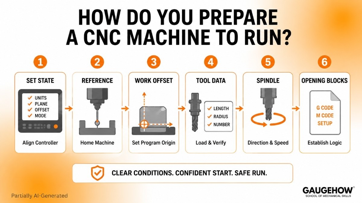
Machine readiness begins with state alignment, because a controller executes active conditions rather than design intent.
Units, active plane, work offset, tool data, spindle direction, and opening sequence all need to support the first meaningful move. When those conditions are explicit, early motion becomes far easier to trust.
Opening blocks do real technical work. They establish execution logic before cutting begins, so coordinate interpretation, spindle behavior, and machine state are not left to assumption.
Set up reference, then connect the program origin to fixture reality, while tool data connects code to actual cutting geometry.
Readiness improves because each condition supports the next one instead of relying on unstated controller memory.
How Does Safe Restart Logic Work?
Safe restart logic begins with one hard fact. Line position alone is misleading.
A cursor may sit on a valid program block while the controller is still missing a required state, and that gap can make the next move behave very differently from what the text appears to say.
Controller state has to be rebuilt in a deliberate order. The active tool must match the next sequence. Work offset must match the setup reference. Units, plane, and active mode must match file expectations.
Spindle state and coolant condition must support the next motion. When one of those elements is wrong, the restart confidence collapses because the machine response is being interpreted through the wrong state.
Work offset changes restart confidence more than broad explainers usually admit. A program block only has meaning inside the right coordinate system.
Once the active offset changes, the same line can send motion to a different physical location even though the text has not changed at all. Safe restart, therefore, it depends on the coordinate system, work offset, current position, active mode, and next motion being read as one connected picture.
CAM output also stops helping beyond a certain point. CAM can generate a valid path. CAM cannot tell whether a live machine still holds the exact controller state needed for a mid-program resume.
Local edits are reasonable when the file section is short, state dependencies are clear, and geometry links are easy to trace. Full reposting becomes smarter once multiple assumptions have shifted, because sequence integrity becomes harder to verify safely once state reconstruction turns murky.
FAQs
What is CNC programming?
CNC programming is the process of turning part intent into executable machine instructions. Geometry, sequence, coordinate system, tool use, and control functions are planned first, then expressed in controller-readable form.
What is G-code in CNC?
G-code is the output language most commonly used to carry programmed motion and machine actions to a CNC controller. It expresses program blocks, interpolation, position, and related commands that the control can execute.
Can CAM replace G-code knowledge?
CAM reduces manual coding, but it does not replace code literacy. G-code knowledge improves file inspection, post-processor judgment, controller awareness, and revision quality once the generated output needs closer engineering review.
What is machine zero vs work zero?
Machine zero is a fixed machine reference. Work zero is a setup reference chosen for a job. Since programmed motion is interpreted through active reference, mixing those two points changes where motion lands physically.
Mechanical Engineering Courses That Industry Actually Uses
Learn Tools of Design & CAD, Analysis & Simulation, Automation & Robotics, and Industry 4.0 used in modern factories.
Join 40+ Mech Courses like GD&T, Siemens NX, SolidWorks, CATIA V5, AutoCAD, ANSYS (FEA & Fluent), ABAQUS, Creo, Fusion 360, CNC Programming, Digital Twins, Python for Mechanical, and Industry 4.0.
Our Courses
Complete Course Library
Access to 40+ courses covering various fields like Design, Simulation, Quality, Manufacturing, Robotics, and more.


