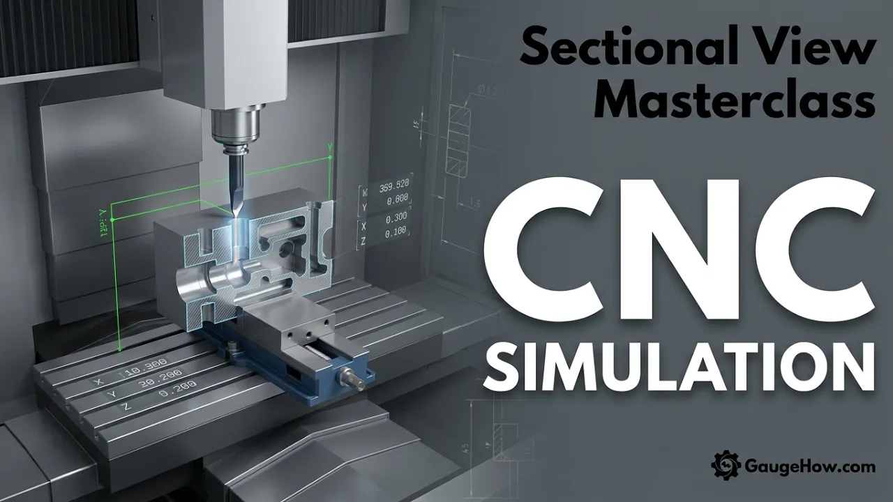

CNC Simulation in CAM: Stop Crashes and Scrap
Learn More in This Video
Subscribe to GaugeHow for More
CNC simulation is a digital machining review inside CAM. Core checks include tool motion, stock change, holder reach, fixture clearance, axis travel, and safe positions. Approval output should show contact points, leftover stock, overcut, and unsafe moves. Shops run it before release because clean geometry alone does not guarantee a safe first cut.
Clear review protects release quality, so the real goal is not animation. The real goal is a better approval decision.
CNC Simulation Checks
Simulation should answer one simple question early. Can planned motion run safely on the intended setup?
A useful review compares motion against stock, fixture, tool assembly, and machine behavior. A simple cutter display is not enough because approval depends on what reaches the machine, not what looks clean on screen. Good output should expose clamp contact, wrong approach direction, missed stock, short retracts, and weak sequence logic.
Approval also needs visible review outputs. Contact zones, stock state, overcut areas, rapid motion paths, and tool change positions should all sit inside the review window. Once those outputs are visible, revision work becomes direct and faster.
What needs approval?
Approval should confirm motion, shape, and setup in one pass. Geometry alone cannot carry release.
Program Review Checks
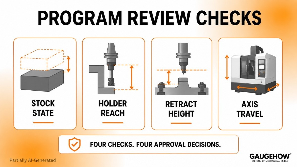
● Stock State: Compare incoming stock form with roughing plan and finish allowance so later passes do not inherit bad material conditions.
● Holder Reach: Confirm usable reach against wall depth, floor depth, and clamp position because safe cutter contact does not guarantee safe holder travel.
● Retract Height: Confirm clearance above stock islands, clamps, and fixtures so links and rapids do not create invisible risk between cuts.
● Axis Travel: Confirm machine limits before the posted output reaches prove-out because motion that fits the CAM may still fail on the real machine.
That named system is important because each line supports a separate approval decision.
Machine Simulation Errors
Machine simulation fails when machine truth and setup truth drift apart. Motion can look valid while the release quality remains weak.
Holder length is one common source. Extra reach may reduce rigidity. Short reach may leave stock. Wrong holder geometry can create side contact near deep walls or workholding. Tool motion may look perfect, but real clearance can still be poor.
Stock definition is another source. Roughing logic, rest passes, and finish allowance all depend on incoming stock shape. Bad stock truth changes cut load, finish behavior, and remaining material. Scrap often begins there.
Post settings create another gap. CAM intent may stay clean, but posted motion can alter retract style, tool call format, axis handling, or safe position logic. Once that changes, machine behavior changes as well.
Where do errors start?
Errors usually start before cutting. Setup sheet drift, stock mismatch, wrong tool assembly, stale post settings, and weak machine data create approval gaps long before first cut.
Toolpath Verification Checks
Toolpath verification should confirm that programmed motion supports drawing intent, surface intent, and sequence intent. Animation alone is not enough.
Path review should look at entry style, exit style, stepdown pattern, stepover spacing, finish allowance, rest areas, and transition logic. Junior engineers improve fastest once review changes from “path exists” to “path behaves correctly.”
What should path review show?
Path review should show where a cutter enters, where stock remains, how walls and floors finish, and whether rapid links pass safely around fixtures and tall stock zones.
Path Quality Checks
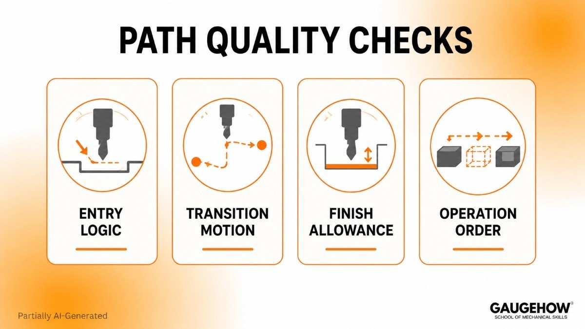
● Entry Logic: Review lead-in direction, plunge style, and approach side so cutter entry stays stable and predictable.
● Transition Motion: Check links, rapids, and retracts because movement between cuts often creates more trouble than the cut itself.
● Finish Allowance: Verify remaining stock for final passes so finishing tools remove the intended material, not roughing leftovers.
● Operation Order: Evaluate machining sequence against drawing requirements because early operations shape stock support, wall stability, and later access.
A named system works better than loose bullets because every point carries engineering meaning.
G-Code Verification Review
G-code verification checks final machine instructions after posting. CAM-side review checks intended motion. Posted code review checks, released motion. That split must be clear because both reviews answer different approval questions.
CAM review can still pass while output shifts later. Tool calls, retract format, spindle commands, axis lines, and safe positions may all change during post-processing. Release confidence should never stop at the CAM display alone.
What changes after posting?
Posted output can change motion behavior, machine response, and safe travel sequence. A clean toolpath does not automatically create clean machine code.
For that reason, code review should be treated as a document review. NC output is a deliverable, so final approval needs alignment across machine choice, setup plan, tool list, and active program revision.
Material Removal Simulation
Stock condition tells the truth about machining sequence. Material removal simulation is the section where roughing, rest work, and finishing finally connect.
A screen can show motion and still hide stock problems. Remaining islands, heavy corners, missed pockets, and extra wall stock often explain why a later pass behaves badly. Once stock state becomes visible after each operation, finishing logic becomes easier to trust.
What does stock reveal?
Stock reveals whether the next operation is entering light cleanup or an unexpected load. That distinction changes finish quality, tool wear, and sequence reliability.
Stock State Checks
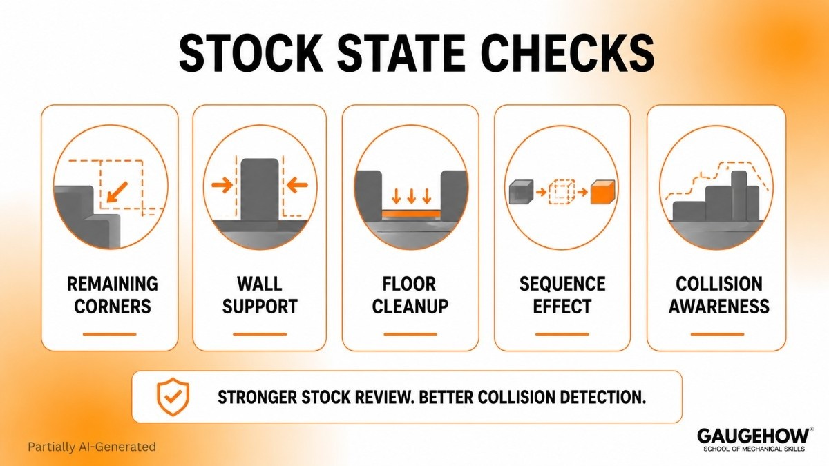
● Remaining Corners: Corner stock after roughing should stay within the load planned for later tools.
● Wall Support: Balanced side stock keeps thin walls stable through finishing passes.
● Floor Cleanup: Full floor contact must be achieved before inspection sign-off moves ahead.
● Sequence Effect: Operation flow should improve the next cut condition, not add variation.
Careful stock review also strengthens collision detection because stock islands and leftover steps can change available space quickly.
How to Prevent CNC Crashes
Prevention comes from sequence, not from one button. Accurate setup comes first. Motion review comes next. Posted-code review follows. Controlled prove-out closes the loop.
Release Checks First
Real value sits here because vendor pages usually stop at feature description. Strong release discipline compares drawing revision, setup sheet, stock form, tool list, holder stack, post version, machine selection, and final NC file in one review window.
Separated documents create blind spots. Joined documents expose them. Revision mismatch, stale post settings, wrong holder stack, and stock drift become much easier to catch once every release item sits together.
Release Gate Checks
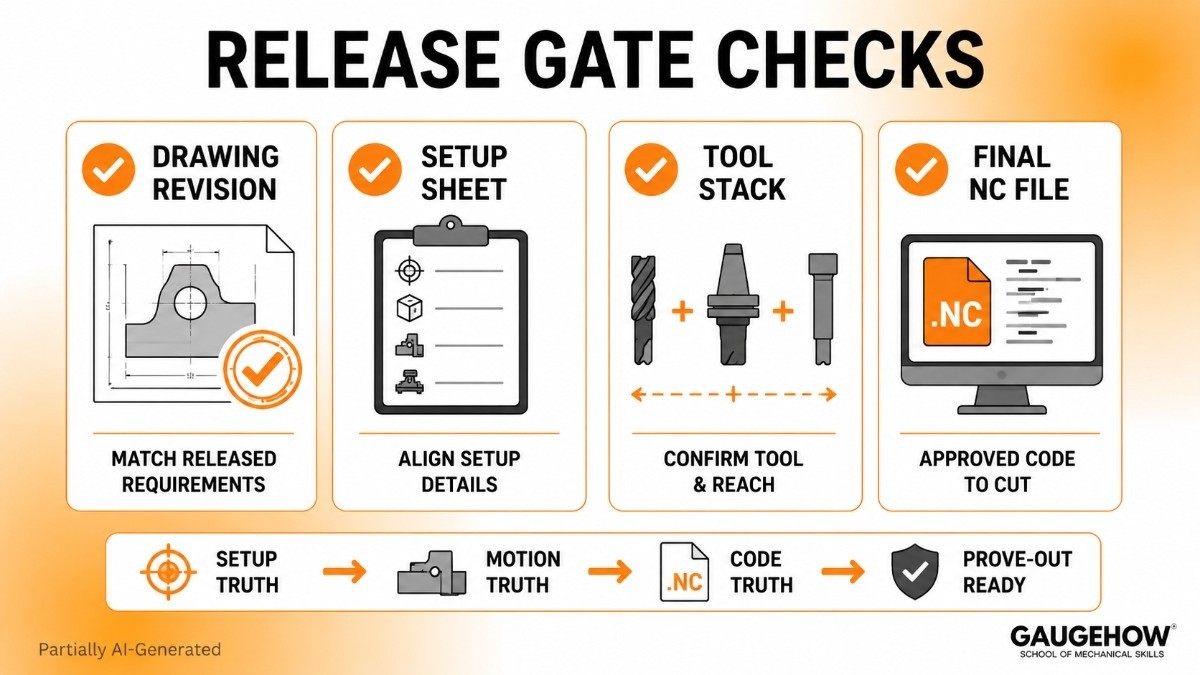
● Drawing Revision: Active geometry must match released features, tolerances, and current approval status before machining logic moves forward.
● Setup Sheet: Origin, stock form, workholding, and machine orientation should align with CAM data and selected machine.
● Tool Stack: Actual setup needs the same cutter, holder, extension, and usable reach defined in the program.
● Final NC File: Posted output should follow the approved sequence, machine selection, and current post version before first cut begins.
Readers searching for how to prevent CNC crashes usually need one method they can use today. Start with setup truth, continue with motion truth, confirm code truth, and only then move into prove-out.
CNC Simulation Software
Good CNC simulation software supports approval quality rather than visual comfort. Useful tools should model machine behavior, stock condition, fixture placement, holder geometry, and motion logic clearly enough to support release decisions.
Shallow tools often look polished but stay generic. Weak machine data, poor stock updates, or vague motion display reduce trust fast. Better systems help engineers compare CAM intent, machine response, and posted output inside one workflow.
What should software show?
Software should show setup truth, motion truth, and approval truth together. A prettier screen is not enough. A cleaner release decision is the actual standard.
Selection should stay practical. Look for realistic setup definition, readable machine behavior, dependable stock updates, and clear machine-code alignment. Good CNC simulation software makes revision work easier because weak motion becomes easier to spot and easier to explain.
FAQ
What is CNC simulation in CAM?
CNC simulation is a digital review of machine motion, stock condition, tool assembly, and setup logic before cutting starts. The purpose is early detection of contact, overcut, missed stock, and unsafe movement before release.
Why can a clean CAM path still fail?
A clean CAM path can still fail because holder reach, stock form, setup data, machine limits, or posted output may not match the intended release package. Approval strength depends on all those elements together.
What does toolpath verification actually check?
Toolpath verification checks entry direction, exit motion, stepdown pattern, remaining stock, finish allowance, and transition safety. Main value is cleaner feature output, better sequence control, and fewer revision surprises during approval.
Why is G-code verification separate from simulation?
G-code verification reviews released machine instructions after posting, while simulation reviews CAM intent before posting. Separation is important because post-processing can change motion behavior, machine response, and safe travel logic.
What should a junior engineer review first?
Start with stock form, setup sheet, holder reach, retract height, and active program revision. Those checks build strong approval habits quickly because setup truth shapes every later decision from path review to final release.
Mechanical Engineering Courses That Industry Actually Uses
Learn Tools of Design & CAD, Analysis & Simulation, Automation & Robotics, and Industry 4.0 used in modern factories.
Join 40+ Mech Courses like GD&T, Siemens NX, SolidWorks, CATIA V5, AutoCAD, ANSYS (FEA & Fluent), ABAQUS, Creo, Fusion 360, CNC Programming, Digital Twins, Python for Mechanical, and Industry 4.0.
Our Courses
Complete Course Library
Access to 40+ courses covering various fields like Design, Simulation, Quality, Manufacturing, Robotics, and more.


