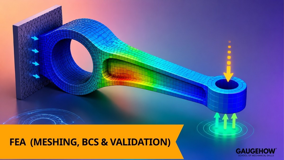
FEA Interview Questions and Answers (Meshing, BCs & Validation)

Deepak S Choudhary
Learn More in This Video
Subscribe to GaugeHow for More
FEA interviews tend to circle back to three things again and again: how well you understand meshing, how carefully you set up boundary conditions, and whether you actually validate your results instead of just trusting whatever the solver spits out.
Basic FEA Concepts
1. What is FEA, and why is it used over hand calculations?
FEA, or Finite Element Analysis, is a numerical method that breaks a complex geometry into smaller elements to approximate how it behaves under load. It's used because real-world parts often have complex shapes and loading conditions that hand calculations simply can't capture accurately. FEA lets engineers predict stress, deflection, and failure risk before building a physical prototype.
2. What is a node and an element in FEA?
A node is a specific point in the mesh where the solver calculates results like displacement. An element is the small region connecting a group of nodes, defined by a shape like a triangle, tetrahedron, or hexahedron. Together, the full collection of nodes and elements forms the mesh that represents the original geometry numerically.
3. What is the difference between linear and nonlinear FEA?
Linear FEA assumes load and response stay proportional, valid for small deformations within a material's elastic range. Nonlinear FEA accounts for large deformations, material plasticity, or changing contact conditions, where the relationship between load and response shifts as the analysis runs. Nonlinear analysis takes more computation and more careful setup to get right.
4. What is the difference between static and dynamic FEA?
Static analysis assumes loads are applied gradually and inertia effects are negligible, giving one equilibrium solution. Dynamic analysis accounts for time-dependent effects like inertia and damping, needed for impact, vibration, or rapidly changing loads. Choosing the right type depends on how quickly the load changes relative to the structure's natural response.
5. What is a degree of freedom (DOF), and why does it matter for model size?
A degree of freedom represents an independent way a node can move or rotate, like translation in X, Y, Z or rotation about those axes. The total DOF count across a model directly affects how large and computationally expensive the analysis becomes. More elements or higher-order elements both increase total DOF significantly.
6. What is the difference between shell, solid, and beam elements?
Shell elements suit thin-walled parts where thickness is much smaller than the other dimensions, like sheet metal. Solid elements suit thick, bulky geometries where through-thickness detail matters. Beam elements suit long, slender members like frames, where cross-sectional behavior isn't the main focus.
Meshing
7. Why is meshing considered one of the most important steps in FEA?
Meshing directly determines how accurately the model captures real geometry and stress behavior, since the solver only sees the discretized mesh, not the original CAD shape.
A poorly built mesh can produce results that look reasonable but are numerically unreliable. Good meshing judgment is often what separates an experienced FEA engineer from a beginner.
8. What is the difference between structured and unstructured mesh?
A structured mesh follows a regular, grid-like pattern, generally offering better accuracy and faster solving on simple geometry. An unstructured mesh uses irregularly arranged elements, like tetrahedra, which handle complex geometry more easily but can be less efficient. Many real models use a mix of both depending on the region's complexity.
9. What is mesh convergence, and how do you perform a convergence study?
Mesh convergence means refining the mesh repeatedly and comparing results until further refinement no longer meaningfully changes the answer. A convergence study typically involves running the same model at two or three mesh densities and plotting a key result, like peak stress, against element count. Once the result stabilizes, you can trust that the mesh density is sufficient.
10. What mesh quality metrics are commonly checked before solving?
Common metrics include skewness, aspect ratio, and orthogonal quality, all of which describe how well-shaped individual elements are. Distorted or highly skewed elements introduce numerical error into the solution. Most FEA software flags elements outside acceptable quality thresholds before allowing the solve to proceed.
11. What is mesh refinement, and where should it typically be applied?
Mesh refinement uses smaller elements in regions needing higher accuracy, like stress concentrations around holes, fillets, or sharp geometric transitions. Refining the entire model uniformly would be accurate but computationally wasteful. Targeted refinement balances result accuracy against solve time and file size.
12. What is the difference between tetrahedral and hexahedral mesh elements?
Tetrahedral elements are simple, four-sided shapes that mesh complex geometry easily but may need finer resolution for equivalent accuracy.
Hexahedral elements are six-sided, generally more accurate and efficient per element but harder to generate automatically on irregular shapes. The choice often comes down to balancing meshing effort against solve efficiency for a given geometry.
Boundary Conditions
13. What are boundary conditions in FEA, and why are they so critical?
Boundary conditions define how the model interacts with its surroundings, including supports, applied loads, and contact between parts. Incorrect boundary conditions are one of the most common reasons FEA results turn out badly wrong, even with a perfectly good mesh.
They need to genuinely reflect how the real part is supported and loaded.
14. What is the difference between displacement and force boundary conditions?
A displacement boundary condition fixes or prescribes how much a node or surface can move, commonly used to represent rigid supports.
A force boundary condition applies a known load without dictating displacement, used to represent weights, pressures, or external forces. Using the wrong type, or mixing them incorrectly, can over- or under-constrain the model.
15. What is an over-constrained model, and why is it a problem?
An over-constrained model has more restraints than physically realistic, which can artificially stiffen the structure and produce unrealistically low stress or deflection results. It often happens when an engineer fixes more surfaces than the part actually contacts in reality.
Reviewing boundary conditions against the actual physical setup is the best way to catch this.
16. What is contact analysis, and why does it add complexity to a model?
Contact analysis models how separate bodies interact, transferring load only where they actually touch, and that contact area itself can change as the parts deform.
It's inherently nonlinear since the contact region isn't known in advance. Contact problems generally need more solver iterations and more careful setup than simple bonded or fixed connections.
17. What is symmetry, and how is it used to simplify boundary conditions?
Symmetry lets you model only a representative portion of a part, like a quarter or half, when both the geometry and loading are symmetric, with symmetry boundary conditions applied at the cut planes.
This reduces model size and solve time significantly without sacrificing accuracy. It only works correctly if both geometry and loading are genuinely symmetric, not just the shape alone.
18. What is a rigid body constraint, and when is it used?
A rigid body constraint links a group of nodes to behave as a single rigid object, often used to apply a load or support across a surface without modeling the actual connecting hardware.
It's commonly used at bolted joints, bearing locations, or load application points. Overusing rigid constraints in areas where actual flexibility matters can distort the real stress distribution.
Results Interpretation and Validation
19. How do you interpret von Mises stress results?
Von Mises stress is a single, combined value derived from the full stress state, commonly compared against a material's yield strength to predict yielding in ductile materials. It simplifies a complex multi-axial stress condition into one comparable number.
It isn't appropriate for brittle materials, which fail by a different mechanism and need a different stress measure.
20. What is factor of safety, and how is it calculated?
Factor of safety is the ratio of a material's allowable strength to the actual stress predicted by the analysis, showing how much margin exists before failure.
A factor of safety above 1 generally indicates a theoretically safe design under the modeled loading. The required minimum factor of safety varies by industry and how confident the team is in the loading assumptions.
21. What is a stress concentration, and how should it be handled in results?
A stress concentration is a localized spike in stress, typically at geometric discontinuities like holes, fillets, or sharp corners. FEA captures these accurately if the mesh is fine enough in that region, since sharp geometry naturally amplifies local stress. Ignoring stress concentrations is a common cause of unexpected fatigue failures in real parts.
22. How do you validate FEA results against reality?
Validation typically means comparing simulation results against physical test data, simplified hand calculations, or published reference solutions for similar problems. It confirms the model setup, boundary conditions, and assumptions actually reflect real-world behavior. Skipping validation is a common reason flawed FEA results end up mistakenly trusted.
23. What is a stress singularity, and why shouldn't you trust the peak value at one?
A stress singularity occurs at a perfectly sharp corner or point load, where predicted stress increases without bound as mesh is refined, rather than converging to a real value. It's a numerical artifact, not a physical result. The fix is usually adding a realistic fillet radius or distributing a point load over a small area, then refining the mesh until the result stabilizes.
24. What is the difference between principal stress and von Mises stress, and when would you use each?
Principal stresses are the actual maximum and minimum normal stresses on a specific plane with no shear component, useful for understanding directional stress behavior.
Von Mises stress combines all stress components into a single scalar value for comparing against yield strength. Different failure theories rely on different stress measures depending on whether the material is ductile or brittle.
Troubleshooting and Practical Scenarios
25. A model shows unexpectedly high stress at a sharp corner. What would you check first?
Sharp corners are a classic source of stress singularities, where stress climbs without bound as mesh refines rather than reflecting real physical behavior. Check whether the geometry should actually have a small fillet that was simplified away during CAD cleanup.
If a fillet genuinely exists, refine the mesh locally and confirm the stress stabilizes instead of continuing to increase.
26. Two engineers get different results for the same part using different mesh densities. How do you resolve it?
Run a proper mesh convergence study on both models to see which result, if either, has actually stabilized with refinement. The coarser mesh is likely under-resolving a stress concentration, producing an artificially low or unreliable result.
The correct answer is whichever mesh density demonstrates a converged, mesh-independent result.
27. Your solver won't converge, and the model keeps failing partway through. What would you investigate?
Start by reviewing boundary conditions for unintentional over- or under-constraint, since both can cause convergence failure. Also check for mesh quality issues, like badly distorted elements, especially in contact or high-deformation regions.
In nonlinear analysis, reducing the load step size can also help isolate whether the issue is a true instability or just a numerical convergence difficulty.
28. An FEA result predicts the part is safe, but a similar part has failed in the field. How would you investigate the discrepancy?
Start by reviewing whether the actual loading conditions and supports in the field genuinely match what was assumed in the model, since real-world conditions often differ from simplified assumptions.
Also check whether fatigue, a load case the static analysis might not have captured, could be the real cause of failure. Comparing the failure location against any predicted stress concentrations in the model is usually a good first clue.
29. You're asked to reduce solve time on a large model without significantly sacrificing accuracy. What would you try?
Consider simplifying geometry that doesn't meaningfully affect results, like removing small non-structural features, and applying symmetry where the geometry and loading genuinely allow it.
Coarsening the mesh in low-interest regions while keeping refinement near critical areas also helps balance speed and accuracy. Scripting repetitive setup or post-processing steps, for example using MATLAB, can also save significant time across multiple model iterations.
30. What's the most common mistake students or new FEA engineers make?
The most common mistake is trusting results simply because the solver finished without checking mesh convergence, reviewing boundary condition accuracy, or sanity-checking the output against expected physical behavior.
A close second is treating boundary conditions as a quick formality instead of the most important setup decision in the whole model. Both come from rushing toward a colorful contour plot before validating what's actually behind it.
Frequently Asked Questions
Q: Is FEA a good specialization for mechanical engineering students?
A: Yes FEA skills are in steady demand across automotive, aerospace, and industrial design, and engineers who genuinely understand meshing and boundary conditions are valued well beyond just knowing the software interface.
Q: Which FEA software should I learn first as a student?
A: Starting with a widely used general-purpose tool, like FEA with ANSYS, gives you a strong foundation, since the core concepts transfer well to other platforms like ABAQUS CAE once you understand them.
Q: How much meshing detail should I expect to be asked about in a fresher interview?
A: Expect questions on mesh convergence, quality metrics, and refinement strategy at a conceptual level, since interviewers often use these to check whether you understand why meshing matters, not just how to click through a meshing tool.
Q: Do I need to know nonlinear FEA for an entry-level role?
A: Not in deep detail, but you should understand the conceptual difference between linear and nonlinear analysis, since interviewers commonly ask this even for entry-level positions.
Q: How should I structure my answers as a fresher candidate?
A: Keep answers short, specific, and grounded in the physical reasoning behind a concept rather than memorized definitions. Interviewers respond better to clear, applied thinking than to long, recited answers.
Conclusion
FEA interviews consistently come back to a few core ideas: building a mesh that's actually fine enough to trust, setting boundary conditions that genuinely reflect real-world supports and loads, and validating results instead of accepting whatever number the solver produces.
If you can explain those fundamentals clearly and reason through a troubleshooting scenario, you'll be well prepared for almost any question an interviewer asks.
To turn this preparation into job-ready skills, explore GaugeHow's FEA with ANSYS course and ABAQUS CAE course, or browse all engineering courses. You can even start free today. Good luck you've got this.