GD&T Interview Questions PDF: 40 Most Asked Q&A with Answers


Deepak S Choudhary
Learn More in This Video
Subscribe to GaugeHow for More
Getting called for a design, quality, or manufacturing engineer interview and seeing "GD&T" on the job description can feel intimidating. The good news is that most interviewers ask from a fairly predictable pool of questions they want to know if you actually understand tolerance zones and datums, not just the textbook definitions.
GD&T Fundamentals & Datums
1. What is GD&T?
GD&T stands for Geometric Dimensioning and Tolerancing. It is a symbolic language used on engineering drawings to describe the allowable variation in the size, form, orientation, and location of a part's features.
Instead of just saying a hole is "10 mm," GD&T tells you exactly how much a hole can shift, tilt, or bend and still work in the assembly. It is standardized under ASME Y14.5 in the US and ISO 1101 internationally you'll build this fluency in GaugeHow's GD&T and Engineering Graphics course.
2. Why is GD&T used instead of conventional (plus/minus) tolerancing?
Plus/minus tolerancing only controls size it says nothing about how straight, flat, or centered a feature actually is. GD&T adds control over form, orientation, and location, so two parts made in different factories will still assemble correctly.
It also removes ambiguity, because every symbol has one fixed meaning, unlike a note written in words. This is why GD&T is the global standard for functional, assembly-critical parts.
3. What is a datum in GD&T?
A datum is a theoretical, perfect reference a plane, line, or point used as the origin for measuring other features. Think of it as the "zero" from which every other dimension is checked. Datums are usually the surfaces that touch the mating part or fixture in real use, not just any convenient face. They are labeled with capital letters (A, B, C) inside a small box on the drawing.
4. What is a Datum Reference Frame (DRF)?
A Datum Reference Frame is the imaginary 3D coordinate system built from three mutually perpendicular datum planes. It gives a part six degrees of freedom to lock three rotations and three translations.
Once the DRF is established from the primary, secondary, and tertiary datums, every toleranced feature is measured relative to that fixed frame, not to the physical part sitting on a table.
5. What are primary, secondary, and tertiary datums?
The primary datum contacts the reference surface at a minimum of three points and controls the most degrees of freedom, usually orientation. The secondary datum contacts at two points and locks another rotation plus a translation. The tertiary datum touches at one point and locks the last remaining degree of freedom. Together, all three fully constrain the part in space.
6. What are the parts of a Feature Control Frame (FCF)?
A feature control frame reads left to right in compartments: the geometric characteristic symbol first (like flatness or position), then the tolerance value, sometimes preceded by a diameter symbol, then a material condition modifier if used, and finally the datum references in order of precedence. For example, a position callout might read: Position | Ø0.2 | M | A | B | C.
Material Condition Modifiers (MMC, LMC, RFS)
7. What is Maximum Material Condition (MMC)?
MMC is the condition where a feature contains the most material possible within its size limits the largest allowable shaft or the smallest allowable hole.
When MMC is applied to a tolerance, the part gets extra "bonus" tolerance as the feature departs from that worst-case size. It's marked with the circled "M" symbol in the feature control frame.
8. What is Least Material Condition (LMC)?
LMC is the opposite of MMC it's the condition where a feature has the least material, meaning the smallest shaft or the largest hole.
LMC is used less often than MMC, typically to control minimum wall thickness or edge distance. It is shown using the circled "L" symbol and also allows bonus tolerance as the feature size moves away from LMC.
9. What is RFS (Regardless of Feature Size)?
RFS means the geometric tolerance applies at every size the feature could actually be, with no bonus tolerance given for size variation.
Since 1994, RFS is the default condition in ASME Y14.5 whenever no modifier symbol is shown, so you rarely see the old RFS symbol on newer drawings. It gives the tightest, most conservative control of the three material conditions.
10. What is bonus tolerance?
Bonus tolerance is extra positional or geometric tolerance a feature earns when it departs from MMC (or LMC). As a hole gets larger than its MMC size, for instance, it has more room to be off-center and still assemble, so that extra room is added to the stated tolerance.
This is one of the most practical cost-saving ideas in GD&T because it allows more parts to pass inspection without any risk to function.
Form Controls
11. What is Flatness?
Flatness is a form control that limits how much a single surface can vary from a perfect plane. It does not need a datum reference because it only compares the surface to itself. The tolerance zone is the space between two parallel planes, and every point on the real surface must fall inside that zone.
12. What is Straightness?
Straightness controls how much a line element on a surface, or the derived median line of a cylindrical feature, can deviate from a perfect straight line. Surface straightness uses a 2D tolerance zone between two parallel lines.
Axis straightness, often applied with MMC, uses a cylindrical tolerance zone and is common on pins and shafts.
13. What is Circularity (Roundness)?
Circularity controls how close a cross-section of a round feature is to a perfect circle, checked independently at every slice along its length.
It does not control the whole cylinder, only each individual circular cross-section. The tolerance zone is the space between two concentric circles at that cross-section.
14. What is Cylindricity?
Cylindricity is a combined control of roundness, straightness, and taper across the entire cylindrical surface at once, not slice by slice.
It is one of the strictest form controls in GD&T because a part must satisfy circularity and straightness simultaneously along its full length. The tolerance zone is the space between two concentric cylinders.
Profile Controls
15. What is Profile of a Line?
Profile of a line controls the shape of a 2D cross-section of a surface, such as an airfoil or contour, compared to the true, basic profile defined on the drawing.
The tolerance zone is a strip of uniform width that follows the theoretical curve. It can be applied with or without datum references depending on whether orientation and location also need control.
16. What is Profile of a Surface?
Profile of a surface is the same idea as profile of a line but applied to a full 3D surface instead of a single cross-section. It is one of the most powerful GD&T symbols because it can simultaneously control form, orientation, and location in a single callout when referenced to datums.
This makes it very popular on sheet metal, castings, and complex free-form surfaces.
Orientation Controls
17. What is Angularity?
Angularity controls how precisely a surface, axis, or line is held at a specified angle (other than 90°) relative to a datum. The angle itself is shown as a basic dimension, and the tolerance zone is the space between two planes tilted at that basic angle. It is an orientation control, so it always needs at least one datum reference.
18. What is Perpendicularity?
Perpendicularity controls how close a surface or axis is to being exactly 90° to a referenced datum. It is another orientation control, so a datum is always required in the feature control frame. The tolerance zone is the space between two parallel planes set exactly perpendicular to the datum.
19. What is Parallelism?
Parallelism controls how close a surface or axis stays parallel to a datum plane or axis, without any tilt. Like angularity and perpendicularity, it is an orientation control and always references a datum. The tolerance zone is two parallel planes (or a cylinder, for an axis) oriented exactly parallel to the datum.
Category 6: Location Controls
20. What is Position Tolerance?
Position tolerance is the most widely used GD&T symbol, and it controls the location of a feature's axis, center plane, or center point relative to datums. It replaces old-style coordinate tolerancing with a round or cylindrical tolerance zone, which gives about 57% more usable tolerance area than a square box for the same limits. Position is almost always used together with MMC to allow bonus tolerance.
21. What is Concentricity?
Concentricity controls whether the median points of a feature's cross-sections share the same center as a datum axis. It is rarely used today because it requires checking the derived median points, which is extremely difficult and expensive to measure.
Most companies now use position or runout instead to control the same kind of relationship.
22. What is Symmetry?
Symmetry controls whether the median points of two opposed features are centered on a datum plane. Like concentricity, it is based on derived median points, so it is hard to measure and has largely been replaced by position tolerance with a center-plane datum in modern practice.
Runout Controls
23. What is Circular Runout?
Circular runout controls surface variation of a rotating feature at a single cross-section, checked while the part is spun a full 360° around a datum axis. It combines the effects of circularity and coaxiality at that one slice. It is commonly used on shafts, wheels, and rotating machine parts to catch wobble.
24. What is Total Runout?
Total runout is the same idea as circular runout, but the indicator sweeps along the entire length of the surface while the part rotates, not just one cross-section. It combines circularity, straightness, coaxiality, and taper into a single control. It is a stricter, more complete check than circular runout.
25. What is the difference between Runout and Profile?
Runout is always measured with the part rotating about a datum axis, so it only applies to features of revolution like shafts and bores. Profile can be applied to any surface shape, rotating or not, and can independently control form, orientation, and location depending on how it's referenced.
Profile is generally more flexible, while runout is simpler to inspect on a rotating setup.
Advanced Building Blocks
26. What is Virtual Condition?
Virtual condition is the worst-case combined boundary generated by a feature's MMC size and its geometric tolerance acting together. It represents the tightest-fitting envelope the feature could ever produce, which is critical for designing gauges and checking assembly clearance.
Virtual condition is calculated as MMC size plus or minus the geometric tolerance, depending on whether the feature is internal or external.
27. What is a Datum Target?
A datum target is a specific point, line, or small area on a rough or non-flat surface (like a casting) that is used to establish a datum, instead of using the whole surface.
It is shown with a circle divided by a horizontal line, listing the target number and datum letter. Datum targets are essential for parts that don't have a clean, flat reference surface to sit on.
28. What is a Basic Dimension?
A basic dimension is a theoretically exact value used to define the ideal size, shape, or location of a feature, shown inside a rectangular box on the drawing.
It carries no tolerance of its own instead, the tolerance is applied separately through the geometric tolerance in the feature control frame. Basic dimensions are the backbone of position and profile tolerancing.
29. What are the common Tolerance Zone shapes in GD&T?
The tolerance zone shape depends on the callout: two parallel planes for flatness, angularity, perpendicularity, and parallelism; two concentric circles for circularity; two concentric cylinders for cylindricity; and a cylinder or sphere for position, depending on whether one or two dimensions are being controlled. Reading the FCF correctly tells you exactly which shape applies.
30. What is Composite Position Tolerance?
Composite position tolerance uses two (or more) rows under a single position symbol, where the upper row controls the location of a pattern of features relative to datums, and the lower row controls the tighter spacing between the features within that pattern.
It lets engineers separate "how accurately does this whole pattern need to sit" from "how tight does the pattern need to be internally," often saving significant manufacturing cost.
Comparisons, Rules & Real-World Application
31. What is the difference between MMC and RFS?
MMC allows bonus tolerance as a feature's actual size departs from its worst-case material condition, so the effective tolerance grows. RFS applies the stated tolerance at every possible size with no bonus, so it stays fixed and is more restrictive.
MMC is chosen for functional assembly fits, while RFS is chosen when a feature needs tight control regardless of its produced size.
32. What is the core difference between GD&T and conventional tolerancing?
Conventional (plus/minus) tolerancing only controls linear size and creates square or rectangular tolerance zones that don't match how parts actually mate.
GD&T controls size, form, orientation, and location together, using tolerance zones shaped like the real geometry (cylinders, circles, planes). This makes GD&T both more accurate for function and often more forgiving for manufacturing.
33. What are the five categories of GD&T symbols?
The 14 GD&T symbols fall into five categories: form (flatness, straightness, circularity, cylindricity), orientation (angularity, perpendicularity, parallelism), location (position, concentricity, symmetry), runout (circular and total runout), and profile (profile of a line, profile of a surface), which can act as either a form, orientation, or location control depending on datum references.
34. Why does the order of datums (A, B, C) matter?
The order of datums in a feature control frame sets the precedence for how the part is constrained during inspection the primary datum is contacted first and controls the most degrees of freedom, followed by secondary and tertiary.
Swapping the order changes which surface the part is measured against first, which can completely change whether a part passes or fails, even though the physical part hasn't changed at all.
35. What is a Projected Tolerance Zone?
A projected tolerance zone extends a position tolerance zone above the part's surface, into the mating part, instead of confining it to the feature itself commonly used for threaded holes or press-fit pins.
It's shown with the circled "P" symbol and a projection height. This prevents a bolt or pin from binding due to hole tilt that wouldn't have been caught if the zone stayed inside the hole.
36. What is the difference between Profile of a Surface and Flatness?
Flatness only controls a surface's own form, with no datum reference, so it can't say anything about where that surface sits relative to the rest of the part. Profile of a surface, when tied to datums, controls form, orientation, and location together, so it can catch a surface that's flat but tilted or shifted out of place something flatness alone would miss.
37. What is the Envelope Principle (Rule #1)?
Rule #1 states that the form of an individual feature is automatically controlled by its size limits a feature made at MMC must have a perfect form at that boundary, and it's only allowed to lose form as it departs toward LMC. This links size and form together automatically, without needing a separate flatness or straightness callout, unless you want tighter control than the size limits already provide.
38. What is Rule #2?
Rule #2 states that RFS applies automatically to any individual tolerance of size feature (or its datum reference) whenever no modifier symbol is shown, following the 1994 revision of ASME Y14.5. Before that update, RFS had to be explicitly stated. Today, if you see no circled M or L in the feature control frame, RFS is understood by default.
39. Where is GD&T used in real manufacturing and inspection?
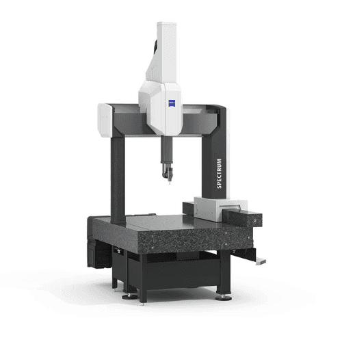
GD&T is used across CNC machining, sheet metal fabrication, casting, injection molding, and assembly to define functional tolerances that CMMs (Coordinate Measuring Machines) can inspect objectively the same measurement logic taught hands-on in GaugeHow's Engineering Metrology & 3D Measurement course.
It drives gauge design, first-article inspection reports (FAIR), and Process Failure Mode and Effects Analysis (PFMEA) in automotive and aerospace supply chains, and it directly shapes how a part gets programmed and toleranced on the shop floor, which is where GaugeHow's CNC Programming course picks up.
Interviewers often ask this to check whether you understand GD&T beyond the classroom.
40. How do you read a complete Feature Control Frame example?
Take the example: Position | Ø0.3 | M | A | B | C. Read it as: "The axis of this feature must fall within a cylindrical tolerance zone of diameter 0.3 mm, at maximum material condition, located relative to primary datum A, secondary datum B, and tertiary datum C, in that order.
" Practice reading two or three real feature control frames out loud before your interview interviewers frequently hand you a drawing and ask you to explain one on the spot.
Frequently Asked Questions
Is GD&T hard to learn for a fresher preparing for interviews?
GD&T is not mathematically hard, but it takes practice to read fluently because it's a visual, symbol-based language rather than a formula-based one. Most freshers get comfortable within a few weeks of consistent practice reading real drawings, rather than only memorizing definitions.
What should I focus on most for a GD&T interview as a fresher?
Focus on datums, feature control frame reading, MMC versus RFS, and position tolerance first, since these come up in almost every interview regardless of industry. Form controls like flatness and circularity are usually asked as a follow-up once the interviewer sees you understand datums.
Do quality engineer interviews ask different GD&T questions than design engineer interviews?
Quality and metrology interviews lean more toward inspection methods, virtual condition, gauge design, and CMM programming logic. Design engineer interviews lean more toward choosing the right symbol and material condition for a given functional requirement. The core 40 questions above cover both angles.
Is ASME Y14.5 or ISO 1101 more commonly asked about in interviews?
In India and the US, ASME Y14.5 terminology is asked most often, so the answers above follow that standard. If you're interviewing with a European or automotive-import company, it's worth also knowing that ISO 1101 uses similar symbols but slightly different rules for default material condition and datum targets.
Conclusion
GD&T interview questions almost always circle back to three ideas: what a datum actually is, how to read a feature control frame, and why MMC gives bonus tolerance. If those three concepts are solid, the rest of the 40 questions above fall into place quickly because they're built on the same logic.
Go through this list two or three times, practice reading real feature control frames out loud, and you'll walk into the interview room prepared for almost anything they throw at you.
If you want to go deeper than interview prep and actually build hands-on GD&T and drawing-reading skills, GaugeHow's GD&T and Engineering Graphics course covers every symbol above with real drawing exercises. Pair it with the Engineering Metrology & 3D Measurement course if your target role involves CMM inspection or quality engineering.