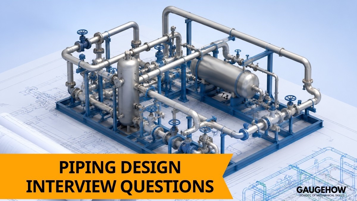
Piping Design Interview Questions and Answers (Oil, Gas & Process)

Deepak S Choudhary
Learn More in This Video
Subscribe to GaugeHow for More
Piping design interviews in the oil, gas, and process industries tend to move fast, and interviewers usually want short, confident answers that show you actually understand how a piping system works in real plant conditions not just textbook definitions.
Piping systems carry hazardous, high-pressure, or high-temperature fluids, so a design mistake isn't just inconvenient, it can be dangerous, which is why interviewers focus on practical reasoning over memorized definitions.
Basic Piping Concepts
1. What is piping design in the context of oil and gas plants?
Piping design is the process of planning the layout, routing, sizing, and support of pipes that carry fluids between equipment in a plant. It balances safety, accessibility, cost, and code compliance. A good design also makes future maintenance and operation easier.
2. What is the difference between a pipe and a tube?
A pipe is sized by nominal pipe size (NPS) and schedule, with wall thickness depending on the schedule chosen. A tube is sized by its actual outside diameter and wall thickness directly. Pipes are generally used in process piping, while tubes are common in heat exchangers and instrumentation.
3. What is a P&ID, and why is it important in piping design?
A P&ID, or Piping and Instrumentation Diagram, shows the process flow, equipment, piping, valves, and instrumentation for a system. It's the master reference document piping designers use to develop layout drawings and isometrics. Every piping decision traces back to information shown on the P&ID.
4. What is the difference between a P&ID and a PFD?
A PFD, or Process Flow Diagram, shows the overall process at a high level with major equipment and flow rates, without piping details. A P&ID adds the detailed piping, valves, instrumentation, and control logic needed for design and construction. The PFD comes first; the P&ID builds on it.
5. What is pipe schedule, and what does it represent?
Pipe schedule is a standardized number that indicates the wall thickness of a pipe for a given nominal size. Higher schedule numbers mean thicker walls, used for higher pressure or more corrosive service. Schedule 40 is one of the most common defaults for general process piping.
6. What is the difference between seamless and welded pipe?
Seamless pipe is manufactured without any weld seam, generally giving it better strength and reliability for high-pressure or critical service. Welded pipe is formed by rolling plate and welding the seam, and is typically more economical for less critical applications. The choice depends on pressure rating, cost, and service criticality.
7. What are the common piping materials used in oil and gas plants?
Common materials include carbon steel for general service, stainless steel for corrosive or high-purity service, and alloy steels like chrome-moly for high-temperature applications. Material selection depends heavily on the fluid being handled, temperature, and pressure. Corrosive or sour service often requires special metallurgy.
8. What is the purpose of a pipe support in a piping system?
Pipe supports carry the weight of the pipe, fluid, and insulation, while also controlling movement caused by thermal expansion. Without proper supports, pipes can sag, vibrate, or stress connected equipment nozzles. Support spacing depends on pipe size, material, and operating conditions.
Valves, Fittings, and Equipment
9. What are the main types of valves used in piping systems?
Common types include gate valves for on/off isolation, globe valves for flow regulation, ball valves for quick shutoff, check valves to prevent backflow, and control valves for automated process control. Each type is chosen based on its specific function in the line. Using the wrong valve type for the job is a common design mistake.
10. What is the difference between a gate valve and a globe valve?
A gate valve is designed for fully open or fully closed operation and offers minimal flow resistance when open. A globe valve is designed for throttling flow and gives better control, but creates more pressure drop even when fully open. Gate valves are for isolation; globe valves are for regulation.
11. What is a check valve, and why is it used?
A check valve allows fluid to flow in only one direction and automatically closes to prevent backflow. It protects equipment like pumps from reverse flow damage and prevents process upsets. Common types include swing check and lift check valves.
12. What is the function of a relief valve in a piping system?
A relief valve automatically opens to release excess pressure when the system exceeds a safe operating limit, protecting piping and equipment from overpressure failure. It's a critical safety device required by code in most pressurized systems. Relief valve sizing is based on the worst-case overpressure scenario.
13. What are flanges, and why are they used in piping?
Flanges are fittings that allow pipes, valves, and equipment to be bolted together and disassembled when needed, unlike welded joints which are permanent.
They're essential wherever maintenance access or equipment removal is required. Flange rating must match the pipe's pressure and temperature requirements.
14. What is the difference between a reducer and a expander in piping?
A reducer decreases pipe size in the direction of flow, typically used when connecting to smaller equipment or instrumentation. An expander increases pipe size, often used to reduce velocity and pressure drop downstream. Both come in concentric and eccentric versions depending on the application.
15. What is a strainer, and where is it typically used?
A strainer is a fitting that removes solid debris from a flowing fluid to protect downstream equipment like pumps or control valves. It's commonly installed just upstream of sensitive equipment. Strainers need regular maintenance since they can become a flow restriction if clogged.
16. What is the purpose of an expansion joint in piping?
An expansion joint absorbs movement caused by thermal expansion, vibration, or misalignment between connected equipment. It prevents excessive stress from being transferred to nozzles, supports, or adjacent piping. They're especially common on long, high-temperature pipe runs.
Design Process, Codes, and Stress
17. What piping codes are commonly referenced in oil and gas design?
The most common code is ASME B31.3 for process piping, alongside B31.4 and B31.8 for liquid and gas pipelines respectively. These codes define design, material, fabrication, and testing requirements. Knowing which code applies to a project is one of the first things a piping engineer must establish.
18. What is piping stress analysis, and why is it performed?
Stress analysis evaluates whether a piping system can safely handle thermal expansion, weight, and other loads without overstressing the pipe or connected equipment nozzles.
It's especially important for high-temperature lines where expansion is significant. Without it, a system can fail or place damaging loads on pumps and vessels.
19. What is the purpose of an isometric drawing in piping design?
An isometric drawing shows a 3D representation of a piping spool in a 2D format, including dimensions, fittings, and welds, used primarily for fabrication and construction. It's the detailed document fabricators actually build from. Strong CAD drafting skills, including comfort with tools like AutoCAD, are essential for producing clean, accurate isometrics.
20. What factors influence pipe routing decisions in plant layout?
Routing decisions consider accessibility for maintenance, avoiding interference with structures and other lines, minimizing pressure drop, and complying with safety spacing requirements. Economic factors like minimizing pipe length and support cost also play a role. Good routing balances all of these rather than optimizing for just one.
21. What is line list, and why is it used in piping design?
A line list is a master document that records every pipeline in a project, including size, material, design pressure and temperature, insulation, and other key data. It's used as a reference across engineering, procurement, and construction. Almost every other piping document is cross-checked against the line list.
22. What is the difference between design pressure and operating pressure?
Operating pressure is the actual pressure the system runs at during normal operation. Design pressure is a higher value, set with a safety margin above operating pressure, used to size piping and select component ratings. This margin accounts for upset conditions and ensures the system has a safety buffer.
23. What is hydrotesting, and why is it performed on piping systems?
Hydrotesting involves pressurizing a piping system with water above its design pressure to verify it can safely hold pressure without leaks before being put into service. It's a required step under most piping codes before commissioning. Any leaks found during the test must be repaired and the system retested.
Troubleshooting and Practical Scenarios
24. A pipe is vibrating excessively during operation. What would you check first?
Start by checking whether pipe supports are spaced correctly and functioning as designed, since inadequate support is a common cause of vibration. Also check for flow-induced vibration from high velocity or turbulence at fittings. Pump or compressor pulsation can also be a contributing source.
25. A piping system is experiencing higher than expected pressure drop. What's your troubleshooting approach?
Review the line for undersized piping, excessive fittings, or a partially closed valve that's restricting flow more than intended. Strainer fouling is another common, easily overlooked cause. Comparing actual conditions against the original design calculations usually narrows it down quickly.
26. A pipe support shows signs of excessive movement or stress marks. What might be the cause?
This often points to thermal expansion that wasn't properly accounted for in the original support design. It can also indicate the pipe is resting on a support that wasn't intended to be a fixed point. A stress re-analysis is typically needed to confirm the root cause.
27. A relief valve is found to be undersized for current operating conditions. What's the risk, and how would you address it?
An undersized relief valve cannot adequately protect the system during an overpressure event, risking equipment failure or a safety incident.
The fix involves recalculating the required relief capacity based on current process conditions and replacing or supplementing the valve accordingly. This is a safety-critical issue that should be addressed immediately, not deferred.
28. A flange connection is leaking intermittently. What would you check?
Common causes include incorrect bolt torque, a damaged or improperly seated gasket, or flange face misalignment. Thermal cycling can also loosen bolts over time on high-temperature lines. Checking bolt torque pattern and gasket condition is usually the first troubleshooting step.
29. Why might a pipeline experience corrosion faster than expected?
This is often due to the actual process fluid being more corrosive than originally assumed, or insufficient material selection for the service conditions. Inadequate or damaged coating and lining can also accelerate corrosion. A metallurgical review against actual operating data usually clarifies the cause.
30. What's the most common mistake students or new piping engineers make?
The most common mistake is treating the P&ID as a formality instead of the authoritative source for every design decision, leading to layout or sizing errors. A close second is overlooking thermal expansion effects on long or high-temperature lines until stress problems show up later. Both come from not connecting process information to physical design early enough.
Frequently Asked Questions
Q: Is piping design a good career path for mechanical engineering students?
A: Yes it's a core discipline in oil, gas, and process industries with strong, steady demand, and experienced piping engineers are valued for the depth of practical and code knowledge the role requires.
Q: What's the difference between a piping engineer and a piping designer?
A: A piping engineer typically handles stress analysis, material selection, and code compliance, while a piping designer focuses on layout, routing, and isometric drawings. In smaller teams, these roles often overlap significantly.
Q: Do I need to know ASME B31.3 in detail for a fresher interview?
A: Not in deep detail, but you should understand what it covers and why it matters, since interviewers commonly ask conceptual questions about code applicability even for entry-level roles.
Q: What software should I be comfortable with before a piping design interview?
A: Familiarity with 2D CAD tools like AutoCAD for layout and isometric drawings is a good starting point, alongside basic exposure to 3D plant design software where possible. Practical drafting comfort matters more than memorized commands.
Q: How should I structure my answers as a fresher candidate?
A: Keep your answers short, specific, and grounded in reasoning rather than memorized definitions. Interviewers respond better to clear, applied thinking than to long, recited answers.
Conclusion
Piping design interviews in oil, gas, and process industries consistently come back to a few core ideas: understanding the P&ID as the source of truth, knowing how valves and fittings function in a real system, and recognizing how thermal expansion and code requirements shape every design decision.
If you can explain those fundamentals clearly and reason through a troubleshooting scenario, you'll be well prepared for almost any question an interviewer asks.
Want to sharpen the drafting skills behind these answers? Explore GaugeHow's AutoCAD course.