Plastic Mould Design Interview Questions and Answers

Deepak S Choudhary
Learn More in This Video
Subscribe to GaugeHow for More
Mould design interviews exist to check whether you understand the physical behavior of plastic shrinkage, flow, cooling and how that behavior shapes every design decision in the tool. A mould that looks correct on a drawing can still fail in production if gate placement, venting, or cooling weren't thought through properly.
Since most mould geometry is built around tight tolerances, it also helps to be comfortable with GD&T and Engineering Graphics fundamentals before your interview.
Basic Concepts
1. What is plastic mould design?
Plastic mould design is the process of engineering a tool that shapes molten plastic into a finished part through injection moulding. It involves designing the cavity, core, runner system, cooling channels, and ejection mechanism. The goal is a mould that produces consistent, defect-free parts across thousands of cycles.
2. What are the main components of an injection mould?
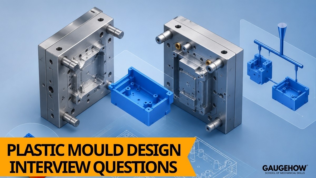
The core components are the cavity and core (which form the part shape), the runner and gate system (which delivers molten plastic), the cooling system, and the ejector system that pushes the finished part out. Together these define how the mould fills, cools, and releases each part.
3. What is the difference between a two-plate mould and a three-plate mould?
A two-plate mould has a single parting line and is simpler, used for parts where the gate location doesn't need to be hidden. A three-plate mould adds a separate plate to automatically separate the runner from the part, allowing gate placement anywhere on the part surface. The tradeoff is added complexity and cost.
4. What is a parting line in mould design?
The parting line is where the two mould halves meet and separate to release the part. Its position is chosen to avoid visible cosmetic defects, allow proper venting, and ensure the part can be ejected cleanly. Poor parting line placement often shows up as flash or visible witness lines on the finished part.
5. What is shrinkage in plastic moulding, and why does it matter?
Shrinkage is the reduction in part size as molten plastic cools and solidifies inside the mould. Every material has a different shrinkage rate, so mould cavities are deliberately oversized to compensate. Getting shrinkage allowance wrong is one of the most common causes of out-of-tolerance parts.
6. What is the difference between a core and a cavity?
The cavity forms the outer surface of the part, while the core forms the inner surface and any internal features. Together they create the closed space molten plastic fills during injection. Most mould drawings refer to these as separate halves even when they're part of the same tool.
7. What is draft angle, and why is it necessary?
Draft angle is a slight taper added to vertical walls of a moulded part so it can be ejected from the mould without dragging or damage. Without sufficient draft, parts can scuff, stick, or deform during ejection. Typical draft angles range from half a degree to several degrees depending on part depth and texture.
8. What is the difference between hot runner and cold runner systems?
A cold runner solidifies along with the part and is ejected as scrap, requiring regrinding or disposal. A hot runner keeps the plastic in the runner channels molten using heaters, eliminating runner waste and often improving cycle time.
Hot runners cost more upfront but reduce material waste in high-volume production.
Material Flow and Cooling
9. What is gate design, and why is gate location important?
The gate is the entry point where molten plastic enters the cavity, and its location directly affects fill pattern, weld lines, and cosmetic appearance. Poor gate placement can cause incomplete filling, visible flow marks, or warping. Designers choose gate location based on part geometry and flow simulation results.
10. What are weld lines, and what causes them?
Weld lines form where two flow fronts of molten plastic meet and fuse together, often appearing as a visible line and a slightly weaker point in the part. They're caused by multiple gates, holes, or complex geometry that splits the flow. Gate placement and flow analysis help minimize their visibility and structural impact.
11. What is the function of the cooling system in a mould?
The cooling system circulates water or coolant through channels in the mould to remove heat from the molten plastic quickly and uniformly. Even cooling reduces cycle time and prevents warping caused by uneven shrinkage. Poorly designed cooling is one of the leading causes of dimensional inconsistency in moulded parts.
12. What is warping in injection moulded parts, and what causes it?
Warping is the distortion of a part's shape after ejection, usually caused by uneven cooling rates across different sections of the part. Thick sections cool slower than thin ones, creating internal stress that pulls the part out of shape. Balanced wall thickness and uniform cooling channel layout help prevent it.
13. What is venting in mould design, and why is it needed?
Venting allows trapped air to escape the cavity as molten plastic fills it, preventing burn marks, short shots, or voids. Vents are typically very shallow channels along the parting line that let air out but not molten plastic. Insufficient venting is a common, often overlooked cause of part defects.
14. What is the significance of wall thickness uniformity in part design?
Uniform wall thickness ensures consistent cooling and shrinkage across the part, reducing the risk of warping, sink marks, and internal stress. Sudden thickness transitions create uneven cooling and visible surface defects. Designers often work closely with mould engineers to adjust part geometry for moulding feasibility.
15. What causes sink marks on a moulded part?
Sink marks appear as small depressions on the surface, usually opposite thick sections like ribs or bosses, where the material cools and shrinks unevenly. They happen because the thicker area retains heat longer than the surrounding thin wall. Reducing rib thickness relative to wall thickness is the most common fix.
16. What is flow simulation, and why is it used in mould design?
Flow simulation software predicts how molten plastic will fill the cavity, helping designers identify potential weld lines, air traps, and fill imbalances before the mould is manufactured.
It's a critical step for complex or high-value tools where a design mistake would be expensive to correct afterward. Simulation results often drive gate location decisions directly.
Design Process and Tools
17. What CAD software is commonly used for plastic mould design?
Most mould designers use SolidWorks 2024 or similar 3D modeling tools for cavity, core, and full mould assembly design, alongside AutoCAD for 2D detailing and layout drawings. Strong 3D modeling skills, especially in surface and assembly work, make a real difference in this field.
18. What is the typical mould design process from part drawing to finished tool?
It starts with reviewing the part design for mouldability, followed by gate and parting line selection, cavity and core design, cooling layout, and ejection system design. Each stage is checked against the previous one before moving forward. The process usually ends with a design review and tooling drawings released to manufacturing.
19. How is GD&T applied in mould and part design?
GD&T defines acceptable variation for critical part features like flatness, position, and parallelism, which directly influences how tight the mould cavity tolerances need to be. Overly tight tolerances without functional justification drive up tooling cost unnecessarily. Designers who understand GD&T can specify only what's actually needed for the part to function.
20. What is the role of ejector pins in a mould?
Ejector pins push the finished part out of the mould once it has cooled and the mould opens. Their placement is chosen to apply even force without deforming or marking the part, usually on reinforced areas like ribs or bosses. Poor ejector placement is a common cause of visible witness marks or part damage during ejection.
21. What is mould flow balance, and why does it matter in multi-cavity moulds?
Flow balance ensures molten plastic fills every cavity in a multi-cavity mould at the same rate and pressure, producing identical parts from every cavity. An unbalanced runner system causes some cavities to overfill while others underfill. Balanced runner design is essential for consistent quality in high-volume production.
22. What factors influence mould material selection?
Mould material is selected based on expected production volume, the abrasiveness of the plastic resin being moulded, and required surface finish. High-volume tools typically use hardened tool steel, while lower-volume or prototype tools may use aluminum for faster, cheaper manufacturing. Material choice directly affects mould life and cost.
23. What is the difference between a prototype mould and a production mould?
A prototype mould is built quickly and cheaply, often from aluminum, to validate part design before committing to full production tooling. A production mould uses hardened steel and is engineered for long-term durability across hundreds of thousands of cycles. Prototype moulds typically have a much shorter expected life.
Troubleshooting and Practical Scenarios
24. A moulded part is showing visible sink marks near a rib. What would you check?
Start by comparing the rib thickness to the surrounding wall thickness, since ribs thicker than about 60% of the wall are a common cause of sink marks. Also check the cooling time and pressure hold settings, since insufficient packing pressure can make the issue worse. Redesigning the rib geometry is usually the most permanent fix.
25. Parts coming out of the mould are warped inconsistently. What's your troubleshooting approach?
Check for uneven wall thickness first, since this is the most common root cause of warping. Then review the cooling channel layout for uniform heat removal across the part.
If both check out, look at process settings like cooling time and material temperature for inconsistency.
26. A part has a visible weld line that's also structurally weak at that point. How would you address it?
Consider relocating the gate to change the flow pattern and avoid the weld line forming in a critical area. If gate relocation isn't possible, increasing melt temperature or injection speed can sometimes improve weld line strength.
Flow simulation is the most reliable way to test changes before committing to a tooling modification.
27. Short shots are occurring intermittently during production. What could be causing this?
Likely causes include insufficient venting trapping air ahead of the flow front, inconsistent material temperature, or insufficient injection pressure for the part geometry. Venting issues are often the first thing to check since they're a design factor rather than a process variable. Confirming consistent material drying is also worth checking for moisture-sensitive resins.
28. A part is sticking in the cavity instead of releasing with the core during mould opening.
This usually points to insufficient draft angle on the cavity side, or surface texture that's creating excess grip. Polishing or adjusting draft angle on the cavity surface, along with reviewing ejector placement, typically resolves it. It can also be a sign the part design itself needs revisiting for mouldability.
29. Cycle time is longer than expected on a new tool. What design factors might be responsible?
Look first at the cooling channel design, since inadequate or poorly placed cooling lines extend the time needed to solidify the part. Wall thickness that's thicker than necessary also increases cooling time directly. Reviewing both against the original design intent usually reveals where time is being lost.
30. What's the most common mistake students or new mould designers make?
The most frequent mistake is treating wall thickness and gate location as afterthoughts rather than core design decisions made early in the process. This leads to costly redesigns once flow and cooling issues surface in production. The second most common mistake is skipping flow simulation on complex parts to save time, only to find the issue after the mould is already cut.
Frequently Asked Questions
Q: Is plastic mould design a good career path for mechanical engineering students?
A: Yes it's a specialized, consistently in-demand skill across automotive, consumer goods, and electronics manufacturing, and experienced mould designers are valued for the depth of practical knowledge the role requires.
Q: What's the difference between a mould designer and a mould maker?
A: A mould designer creates the engineering design, cavity layout, and tooling drawings. A mould maker manufactures and assembles the physical tool from those drawings, often using CNC machining and EDM. Many engineers gain experience in both areas over a career.
Q: Do I need to know flow simulation software for an entry-level interview?
A: Not always at a deep level, but you should understand what flow simulation is used for and how it influences gate and cooling decisions, since interviewers often ask conceptual questions about it even if you haven't run the software yourself.
Q: What CAD software should I focus on before a mould design interview?
A: SolidWorks for 3D cavity and core modeling, and AutoCAD for 2D layout and detailing, are the two most commonly expected tools. Practical comfort with assembly and surfacing tools matters more than memorized commands.
Q: How should I structure my answers as a fresher candidate?
A: Keep answers short and specific, explaining the reasoning behind a concept in a few sentences rather than reciting a definition. Interviewers respond better to clear, applied thinking than to long, memorized answers.
Conclusion
Plastic mould design interviews almost always circle back to a few core ideas: how plastic flows and shrinks, why gate and cooling placement matter, and how wall thickness decisions ripple through the entire part's quality.
If you can explain those fundamentals clearly and reason through a troubleshooting scenario, you'll be well prepared for nearly any question an interviewer asks.
Want to build the modeling skills behind these answers? Explore GaugeHow's SolidWorks 2024 course.