Applications Of CAD In Mechanical Engineering: 12 Real Uses

Applications of CAD in Mechanical Engineering are the practical work where CAD outputs become partsthat people can build and inspect. You will see 12 real uses first, then the handoffs that create rework: mates, drawings, BOM, and released files.
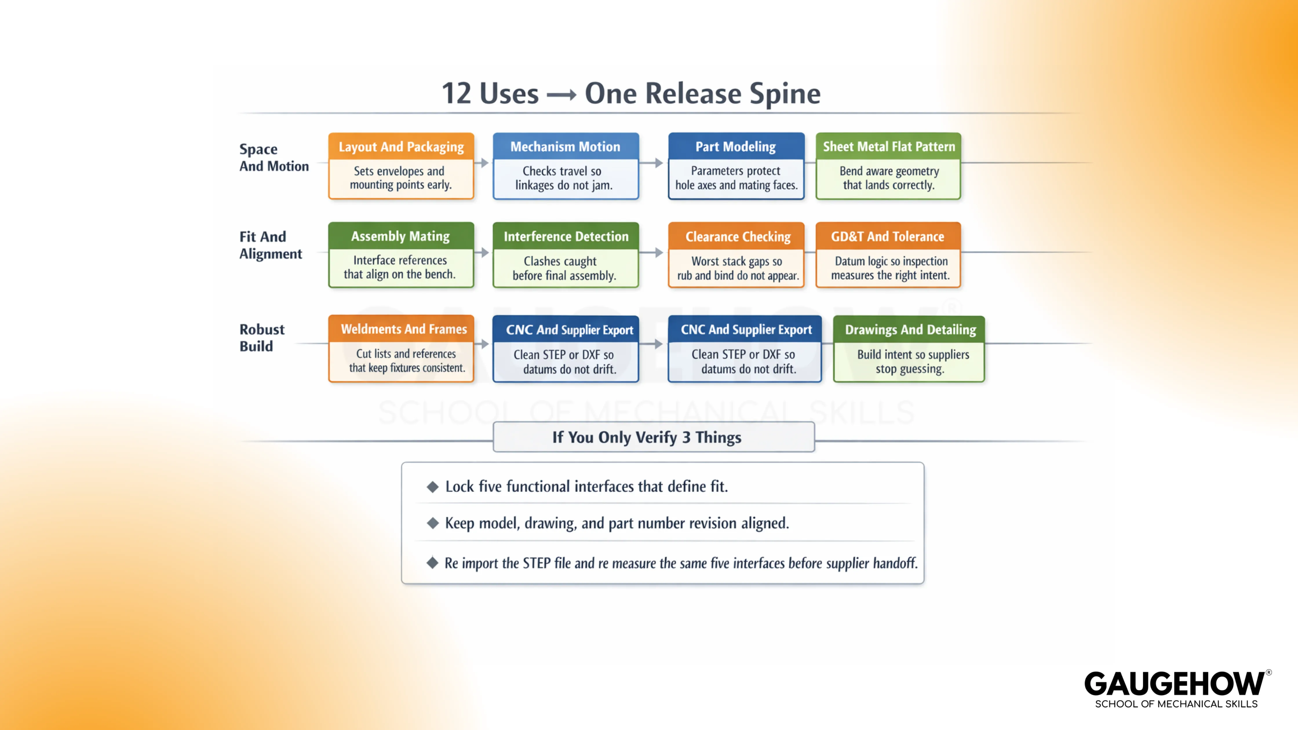
12 Real Uses
1. Layout and Packaging: Sets envelopes and mounting points early, so tools, covers, and harness routes do not collide later.
2. Part Modeling: Locks key dimensions with parameters, so edits do not shift hole axes and mating faces.
3. Assembly Mating: Defines interface references clearly, so parts align on the bench without forcing or shimming.
4. Clearance Checking: Confirms functional gaps at the worst stack, so rub, bind, and noise do not appear after build.
5. Interference Detection: Flags clashes before release, so overlaps are not discovered during final assembly.
6. Drawings and Detailing: Communicates build intent cleanly, so suppliers stop guessing and quoting wrong.
7. GD&T and Tolerance: Constrains acceptance with datum logic, so inspection measures what the design actually intended.
8. Sheet Metal Flat Pattern: Outputs bend-aware geometry, so flat length and flange position land correctly.
9. Weldments and Frames: Carries cut lists and references, so fixtures stay consistent, and distortion stays controlled.
10. Mechanism Motion: Checks travel and envelopes, so linkages do not jam at the one corner case angle.
11. CNC and Supplier Export: Delivers clean STEP or DXF, so setup datums do not drift after translation.
12. BOM and Release Package: Freezes a matched build set, so purchasing, QA, and production share one truth.
If You Only Verify 3 Things
Lock the 3–5 functional interfaces that define fit.
Keep the model, drawing, and part number revision aligned.
Re-import the STEP file and re-measure the same interfaces before supplier handoff.
What CAD Is In Mechanical Work
In mechanical teams, CAD is the act of defining parts and assemblies on a computer, then producing the drawings and released files that the shop will actually touch.
Trouble starts when the model looks right, but the release set drifts across revisions. Run a quick check early: pick one fit-critical interface and confirm the same datums drive it in the model and drawing.
Finish the thought with behavior, not words. Lock the datum scheme to function, then keep references stable so a thickness change or hole move doesn’t quietly shift a locating face.
A team can tolerate slow modeling. A team cannot tolerate files that disagree.
2D CAD vs 3D CAD vs Freeform CAD
2D CAD is drafting used for layouts, schematics, and fabrication profiles, where the drawing is the main contract.
3D CAD is parametric solids and assemblies where dimensions drive geometry, so change can propagate without redrawing everything.
Freeform CAD is surface-driven work used when shape is driven by ergonomics, airflow, styling, or complex blends.
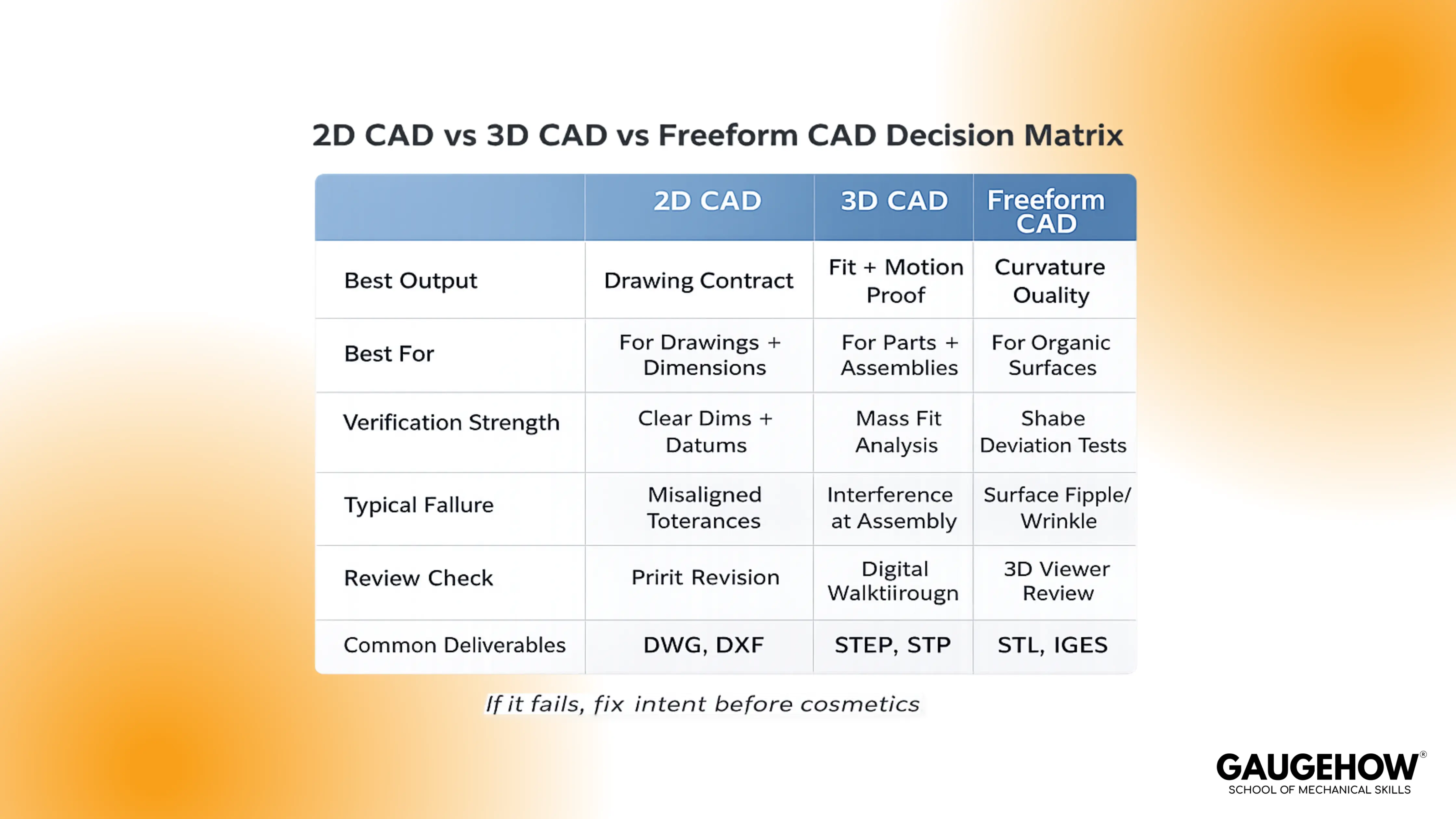
Mismatch creates pain fast. Drafting a part that needs stack control invites ambiguity. Surfacing a part that needs stable datums invites drift. Choose with one check: ask which file inspection will be used to set up, then ensure the modeling method supports that setup cleanly.
MCAD Meaning
MCAD means mechanical CAD: parts, assemblies, drawings, tolerances, and manufacturing handoff.
Confusion happens when “3D modeling” gets treated as the job, while datums, stacks, and inspection setups get treated as admin.
Use one rule to keep it grounded. If the released set cannot be measured without interpretation, the MCAD work is not complete, even if the screen looks perfect.
How CAD Is Used In Engineering
Engineering uses CAD to move from an idea to a released package that can be built repeatedly.
Layout turns into part geometry, part geometry turns into interfaces, interfaces turn into drawings, drawings lock configuration, and files carry that definition into manufacturing and inspection.
Weak teams treat those as separate tasks owned by different people. Strong teams treat them as one continuous flow with the same few checks repeated every time.
That is why the same software can produce either clean builds or endless churn.
Applications Of CAD In Mechanical Engineering: Workflow Spine
Part Definition To Assembly Interfaces
Parts become real when they are located correctly inside an assembly. Face-based shortcuts feel fast in the moment, then a revision moves the “convenient face,” and the mating scheme follows it.
Open the top-level assembly after any fit-critical change and confirm the locating axes and primary datums did not shift. Use CAD for assembly design and interference check the way a build lead would. Pick 3–5 invariant interfaces, like datum planes, bore axes, and mating faces.
Rebuild, then verify those interfaces still land where the rest of the product expects them.
Assembly To Drawing And GD&T
Drawings translate 3D intent into setups people can repeat. Ambiguity shows up as two inspectors getting two answers, both “reasonable,” then production gets stuck in debate.
Ask for the measurement plan before release and make sure it reads like one obvious setup, not an interpretation exercise. Treat CAD for GD&T and engineering drawings as a clarity test, not a symbol test.
Anchor the datum story to function, then confirm the critical features can be measured without calling design. When that holds, inspection stops being a negotiation.
Drawing To BOM And Configuration
A BOM is configuration control wearing a spreadsheet costume. Confusion starts with similar descriptions, a quiet revision mismatch, or an alternate part that was never defined properly.
Check the top 10 line items and verify pthat art number, revision, and quantity match the released set. Keep it blunt and physical. If purchasing can buy the wrong item while believing they did the right thing, the configuration is not controlled.
Tighten naming, lock revisions, and make alternates explicit.
BOM To Manufacturing Handoff Package
Manufacturing rarely opens your native model. The shop uses a release package, a neutral file, and a drawing, and it will build to what those files say, not what you meant.
Open the exact deliverables you are sending out and confirm that the same three interfaces still measure the same. Bring CAD for CNC machining and CAM handoff into the same discipline. A clean toolpath cannot save a bad datum assumption.
Align the manufacturing datum scheme with the drawing, then verify that setup-critical faces and axes survive the handoff.
Release To Prototype And Feedback
First build turns assumptions into facts. Force-fit, pry-bar assembly, repeated supplier questions, and non-repeatable inspection results are not “shop problems.”
They are defined as debt that slipped through release. Use CAD for rapid prototyping and 3D printing as a truth test.
Capture repeated issues, then push the fix upstream into part references, interface definition, drawing clarity, and release file verification. Next release gets faster because the same mistake stops repeating.
CAD In Industry
Different industries punish different misses, but the failure pattern feels familiar. A packaging miss becomes a late clash. A configuration miss becomes a build-to-the-wrong-revision event. A handoff miss becomes scrap because the fixture or setup shifted.
Keep it bench-real: name what gets designed, name how it fails on a build, then run one check that fits inside a minute.
CAD in the Automotive Industry
Automotive work lives on brackets, packaging, and service access around hard constraints.
Clearance gets stolen by the stack, then a harness rubs or a cover needs “extra force” every time. Open the top-level assembly, measure the one clearance that would cause rub, then confirm the locating datums still match the drawing.
CAD in the Aerospace Industry
Aerospace work lives on tight interfaces and strict configuration control across many parts.
Drift shows up as a bracket that fits on one build and fights on the next because revision alignment slipped. Pull the released set and confirm the part number and revision match across the model, drawing, and the file being shared.
CAD In Industrial Machinery
Industrial machinery lives on frames, guards, service access, and alignment across big stacks.
The miss shows up as tool access that “should work” but doesn’t, or alignment that depends on shims nobody planned. Simulate one service task and one alignment interface, then verify that the locating scheme is stable.
CAD In Tooling And Mold Design
Tooling work lives on parting decisions, shutoffs, and surfaces that must actually cut and release.
Surprises arrive when draft or shutoff geometry was assumed, not proven, and the tool path gets ugly fast. Run a quick draft and sanity check, then confirm the parting intent is clear in the released geometry.
CAD In Consumer Products
Consumer products live on snaps, cosmetic gaps, and feel in the hand. Failures appear as squeaks, visible misalignment, or assembly forces that vary by unit.
Check one cosmetic gap at the worst stack, then verify the locating features drive that gap the same way every time.
CAD Vs CAM
CAD defines geometry, tolerances, and the datum story. CAM defines setups and toolpaths that will physically create the surfaces and features. Mismatch happens when the model implies one locating reality and the machining setup uses another.
Keep it simple on the floor. Align the manufacturing datum scheme to the drawing, state the setup intent, then validate the cut result against the few dimensions that determine fit. When those few checks pass, the rest of the process gets calmer.
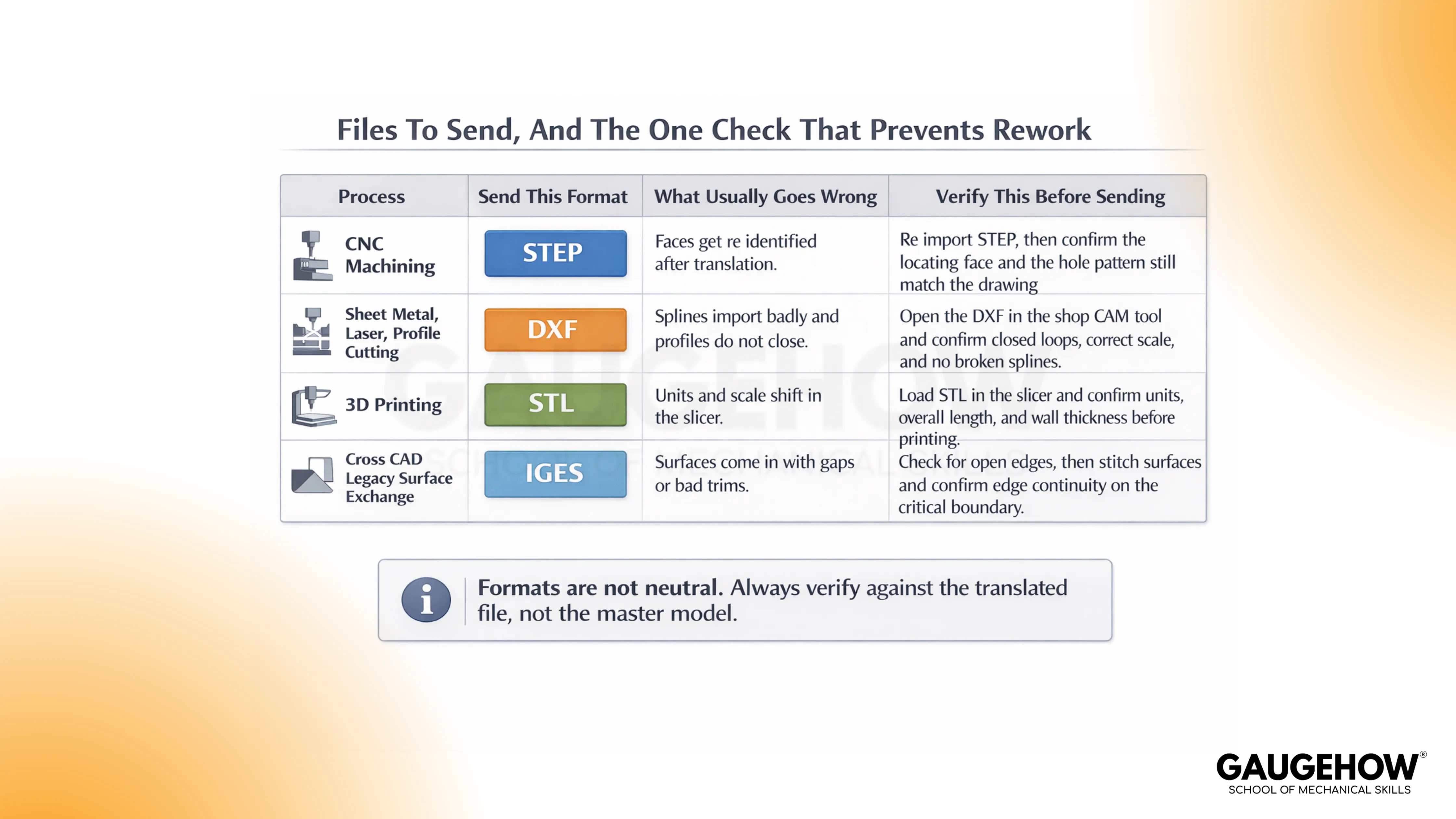
Process-to-format fit saves you from avoidable handoff pain.
Process | Preferred Format | Don’t Do This |
CNC Machining | STEP | Don’t send STL for machined parts unless explicitly agreed |
Sheet Metal / Laser / Profile Cutting | DXF | Don’t export splines without checking the shop’s import behavior |
3D Printing | STL | Don’t assume scale and units are preserved without verifying |
Formats are not neutral. Translation can change face identity, and that is enough to shift where a fixture is located. Verify against the translated file, not the master model.
Also Read: CAD vs CAM vs CAE: Differences You’ll Never Mix Up
Files And Formats
File handoff is where many “good models” start failing quietly. The phrase CAD file formats STEP IGES DXF STL matters because each container can preserve or lose different parts of intent, and the shop will build to what survives the transfer.
Re-import the neutral file, rebuild the datum scheme, and measure the same interfaces before anything leaves your control.
A bracket with a 4-hole locating pattern is a good example. Translation creates a STEP file, the importing system re-identifies faces, and the fixture pins reference a different face identity than you expected.
Hole locations measure “okay” in one setup and still force-fit in assembly because the locating reality shifted.
1. Re-import the neutral file in a clean session.
2. Recreate the same datums and the locating axis used in the drawing.
3. Measure the same 3–5 fit-critical interfaces before supplier handoff.
Conclusion
CAD becomes valuable when the release stays boring. If parts fit once, they should fit every time, so lock 3 to 5 functional interfaces, keep model and drawing revisions aligned, and re-import the STEP you will actually send. These habits turn 12 CAD uses into one clean handoff across design, manufacturing, and inspection. If you want to build that discipline fast, enroll in GaugeHow’s CAD course and practice on shop floor projects with real release checks.
FAQs
Which skills matter most for mechanical CAD work?
Stable references, interface thinking, clear drawings, and disciplined release habits matter more than fancy features. A clean feature tree is nice. A release set that never surprises the shop is better.
How do you prevent a mate from drifting after a design change?
Lock mating intent to datums and axes, not convenient faces. Rebuild after fit-critical edits, then re-check the same few interfaces every time.
What should be checked before sending files to a supplier?
Revision alignment across model and drawing, plus a quick re-import and measurement of a small set of fit-critical interfaces from the file you will send.
Why do two inspectors sometimes get two different results?
Ambiguous setup and datum story. Tighten the drawing so the setup is obvious and repeatable, then ensure the measurement plan reads the same for anyone.
When does a design count as “ready to release”?
Release is earned when manufacturing can build it, and inspection can verify it without interpretation, using the exact deliverables you are shipping.
CAD-CAM-CAE Work Platform
Find or Post CAD, CAM and CAE freelance projects, full-time jobs and Internships.
GaugeHow is the platform built for core engineering work. Whether you need a freelancer for a CAD project, a full-time hire, or an engineering intern,post it here and get matched with the right person.


