What Is CAD? Computer-Aided Design Explained With Examples

Computer-Aided Design (CAD) is the software-driven workflow engineers use to create, control, and revise geometry for review, dimensioning, manufacturing, and inspection. Outputs include 2D drawings, 3D parts and assembly models, and neutral handoff files like STEP or STL.
Engineering ideas only become real when they turn into geometry you can review, revise, measure, and manufacture. What is CAD in that context? It is the workflow that converts intent into precise design deliverables, not just shapes on a screen.
CAD is software used to create and modify design geometry. It produces 2D drawings, 3D models, or both.
Once you see CAD as a deliverable engine, everything gets clearer. You stop chasing commands and start building models that survive change, drawings that communicate intent, and exports that downstream teams can trust.
What Is CAD
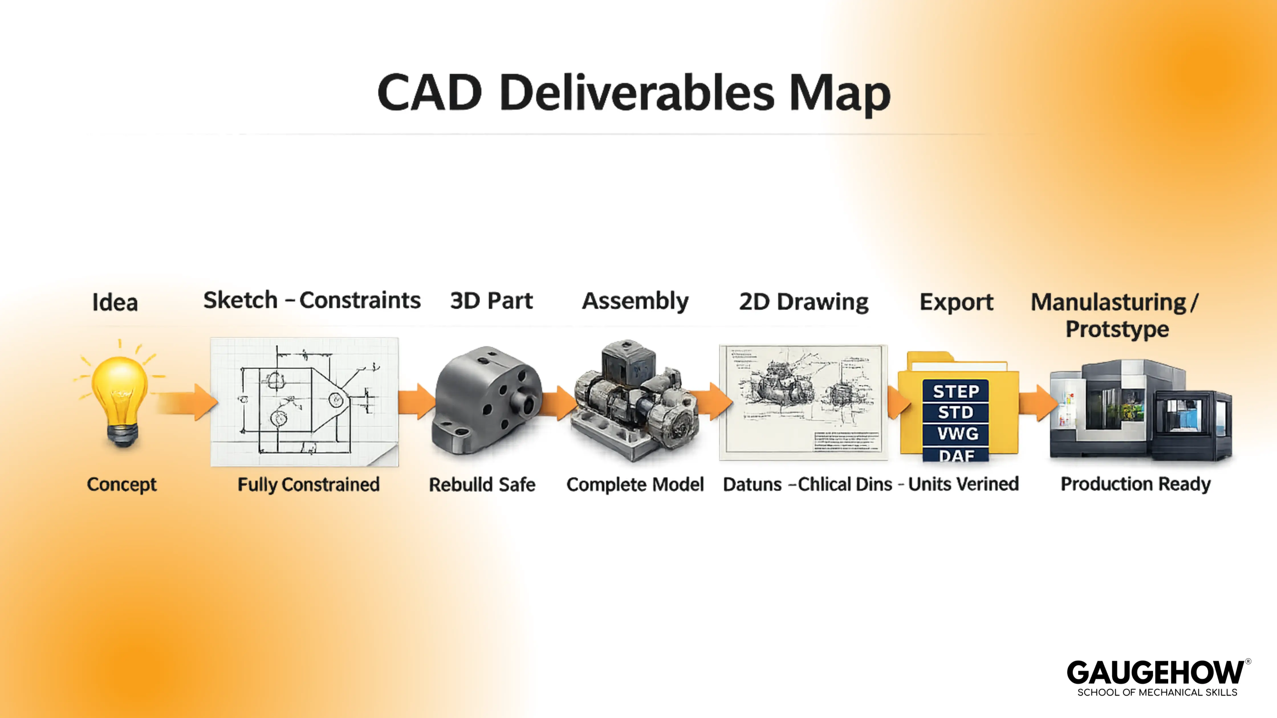
A CAD workflow starts with a design goal and ends with files that other people can use without guessing. That usually means a part model, an assembly when needed, a drawing when manufacturing or inspection needs it, and one or more exports for handoff.
From an engineering standpoint, what is CAD? It is really about the control. Dimensions, constraints, datums, and feature relationships define how geometry behaves when you edit it. A model that looks correct but collapses under revision is not “done”; it is fragile.
That distinction matters because design rarely stays fixed. In real projects, changes arrive from fit checks, cost-down, supplier feedback, and late requirement updates. CAD either absorbs those changes cleanly or creates avoidable chaos in drawings, assemblies, and handoff files.
CAD Definition
A useful CAD definition is a process definition, not a dictionary line. CAD is the controlled creation and documentation of geometry so a design can be reviewed, manufactured, and verified with repeatable results.
CAD Timeline In 7 Lines
Let's dive deeper into the History of CAD:-
1. In the 1960s, interactive computer graphics proved that design could be edited on-screen.
2. By the 1970s, early CAD spread through aerospace and automotive for drafting and layout.
3. During the 1980s, 2D CAD became mainstream on workstations and then PCs.
4. The 1990s then brought parametric 3D solid modeling and assembly workflows into standard practice.
5. In the 2000s, CAD connected tightly with simulation, PLM, and CNC manufacturing chains.
6. Through the 2010s, cloud collaboration and version-controlled models grew fast.
7. More recently, in the 2020s, generative design and AI features started accelerating iteration speed.
In design reviews, CAD quality is judged by intent clarity. Fully constrained sketches, stable references, and a clean feature tree make edits predictable. The moment you can change a key dimension and everything rebuilds without surprises, CAD becomes an engineering asset instead of a fragile file.
That matters because teams do not ship screenshots. Teams ship parts and accountability. A stable CAD model reduces rework, accelerates review cycles, and prevents the “late-night rebuild” problem when a single edit breaks half the features and forces rushed fixes.
How CAD Works In Real Workflows
A typical CAD workflow moves from intent to geometry to documentation. You start with sketches and constraints, build features that create solid or surface geometry, and then produce outputs that support assembly, manufacturing, and inspection.
Under revision pressure, the core principle is parametric intent. Constraints lock behavior, dimensions drive change, and references define what updates safely. When references chain to unstable edges and random faces, rebuild failures become predictable, not random.
That matters because CAD is a change-management tool. If your model is built on stable datums and controlled sketches, you can revise thickness, hole size, or spacing and still keep the design consistent across the model, drawing, and export. If it is built on weak references, every change becomes a risk.
Types Of CAD And Where They’re Used
Types of CAD exist because not every engineering output is the same. Some work is drawing-first, some is model-first, and some demands freeform surface control for complex shapes. Treating all CAD as one bucket is a fast way to learn slowly.
In practice, three categories cover most workflows: 2D CAD, 3D CAD, and Freeform CAD.
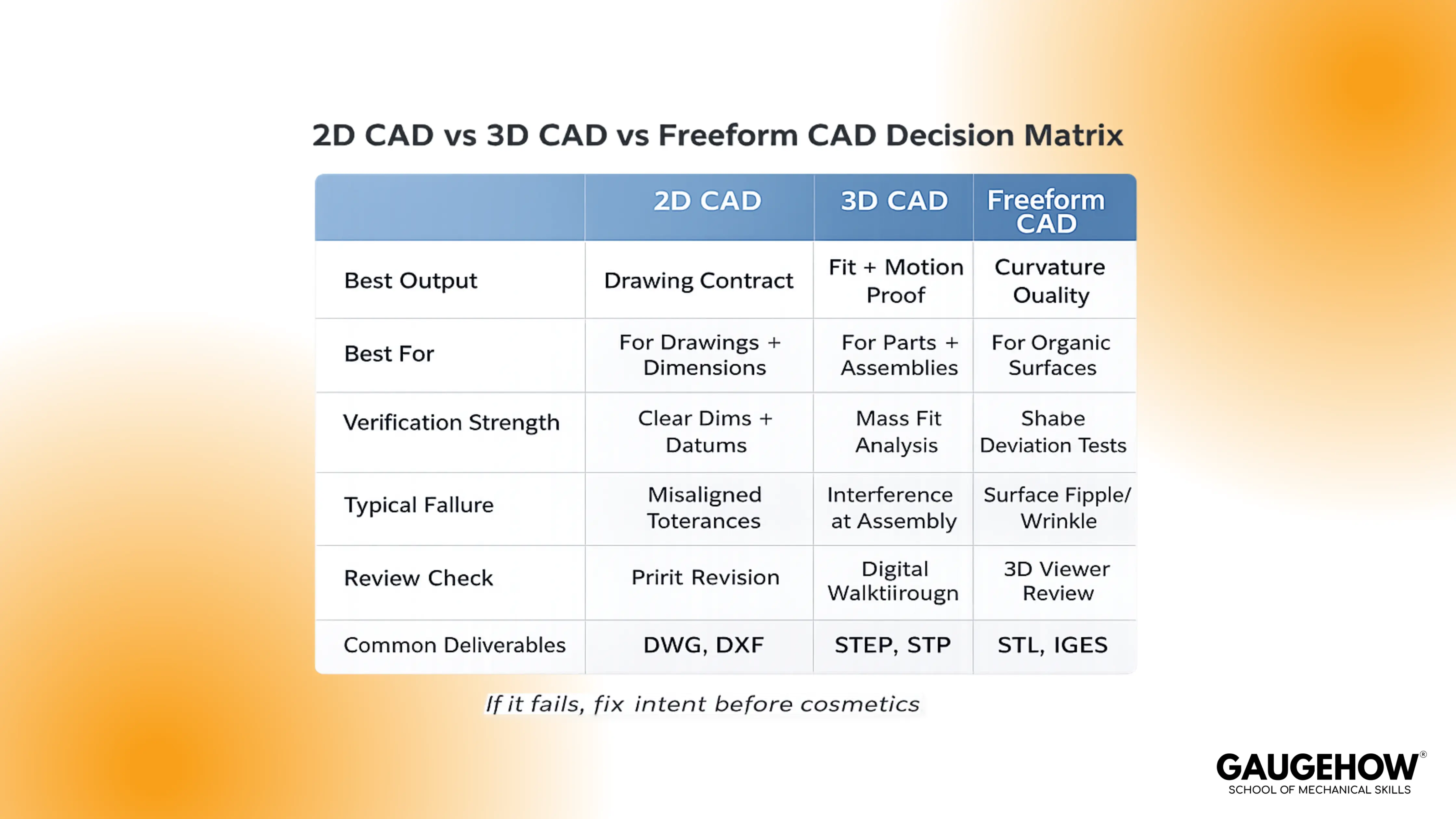
2D CAD focuses on drafting and documentation. 3D CAD focuses on parametric parts, assemblies, and change-safe modeling. Freeform CAD focuses on surface quality, curvature control, and complex forms where continuity matters as much as dimensions.
That matters because tool choice follows verification needs. When packaging, fit, motion, or interference must be verified, 3D CAD is the natural path. When documentation is the contract and geometry is simpler, 2D CAD can be enough. When styling and surface quality drive the product, freeform tools prevent shape compromise.
What Is A CAD Drawing
A CAD drawing is the controlled 2D document that tells manufacturing and inspection what to build and what to verify. It translates a model into views, dimensions, tolerances, datums, notes, and often an assembly bill of materials.
On the shop floor, drawings succeed when they make intent obvious. Datums establish the measurement frame, critical dimensions control fit, and tolerance choices decide whether parts assemble reliably. A drawing that “looks complete” but misses the true controlling dimensions creates rework.
That matters because drawings are where ambiguity becomes cost. A clean model with a weak drawing still fails the handoff. If a teammate cannot manufacture the part using only the drawing and one neutral export, the drawing is not doing its job.
CAD Examples With Input, Output, And Reviewer Checks
Examples become powerful when you treat CAD like a deliverable chain. A good CAD example is not “a shape I modeled,” but “a design I can release,” with outputs and checks that prove it.
In review settings, the fastest way to sound production-ready is to show what you created and what you verified. When edits arrive, a stable model rebuilds, the drawing updates cleanly, and the export remains correct in units and geometry.
That matters because engineers are judged on reliability. If your examples demonstrate change safety, clear documentation, and correct handoff files, you look like someone who can ship work under constraints.
Bracket Part Example
Input → Output → Reviewer Check: Requirements sketch → Part model → Drawing → STEP → Rebuild after thickness change, hole position stays stable, drawing shows datums and critical dimensions.
A simple bracket teaches constraints, reference discipline, and revision safety without hiding behind complexity. A controlled edit, like changing thickness by 20 percent, should not break ribs, fillets, or hole placement.
Assembly Example
Input → Output → Reviewer Check: Parts + mates → Exploded view + BOM → STEP → No accidental degrees of freedom, interference check is clean, rebuild survives part suppression and reactivation.
A small assembly exposes weak mating logic quickly. In design reviews, functional mates beat “looks aligned” mates because they mimic how real hardware locates and constrains.
Sheet Metal Example
Input → Output → Reviewer Check: Sheet metal model → Flat pattern + bend notes → DXF → Thickness update regenerates flat pattern, bend information stays consistent, hole to bend risk is reviewed before release.
A sheet metal part forces you to respect manufacturing behavior. When bend details and flat patterns remain stable under thickness change, your modeling approach is aligned with real production expectations.
Prototype Handoff Example
Input → Output → Reviewer Check: Part model → STL → Printed prototype → Units confirmed, one known feature measures correctly after export, surfaces are acceptable for the intended tolerance.
A prototype export tests unit discipline and surface quality. If the scale is wrong, you waste time and material. If surfaces are messy, you get misleading fit feedback from the prototype.
CAD Vs CAM Vs CAE
Design, validation, and manufacturing are different jobs with different outputs. Confusion happens when teams treat them as interchangeable labels instead of a handoff chain with clear deliverables.
A clean workflow spine is easy to remember and easy to repeat:
CAD → CAE (Validate) → CAM (Make) → Inspection (Verify)
That matters because weak handoffs create late surprises. If CAD models are inconsistent, the CAE setup becomes slow and assumption-heavy. If CAM receives poor geometry or wrong units, the toolpath work becomes repair work. If the inspection lacks a clear drawing and datums, verification becomes an argument instead of a measurement.
Popular CAD Tools And How To Choose
Searching for “best CAD software” often leads to long lists that do not help you choose. A better approach is picking a category that matches your deliverables and your constraints, then learning the workflow deeply enough that switching tools becomes manageable.
In mechanical design, the categories are stable across the industry.
Use-Case Category | Pick This When | Typical Outputs | Examples |
2D Drafting | You are drawing first, and documentation is the main deliverable | DWG/DXF drawings, detailing sheets | AutoCAD, DraftSight, BricsCAD, LibreCAD |
Parametric Mechanical 3D | You need to change safe parts, assemblies, and drawings that update cleanly | Parts, assemblies, drawings, STEP | SOLIDWORKS, Creo, Inventor, Solid Edge, NX, CATIA |
Cloud CAD | You want browser access, team collaboration, and lightweight sharing | Cloud models, drawings, STEP | Onshape, Fusion 360 |
Freeform + Surfacing | Surface quality and curvature continuity matter more than pure dimensions | Class-A surfaces, complex forms | Rhino, Alias (plus surfacing modules in CATIA/NX) |
Open-Source / Entry | You need a free start and smaller projects while learning fundamentals | Parts, drawings, STEP/STL | FreeCAD, LibreCAD |
2D drafting tools focus on drawings. Parametric mechanical CAD tools focus on parts, assemblies, and drawings with change-safe behavior. Cloud CAD tools prioritize collaboration and access. Freeform and surfacing tools prioritize curvature and form control. Open-source CAD tools can be a practical starting point for fundamentals and smaller projects.
That matters because outcomes beat brand names. If your goal is job-ready competence, build skills that transfer: constraints, datums, assembly discipline, drawing intent, and export verification. Once those fundamentals are strong, the software interface becomes a smaller problem than your engineering decisions.
The Release Gate Standard
A stable CAD file is not “done” when it looks correct once. It is “done” when it is safe to revise, safe to document, and safe to hand off without hidden traps. This is where most CAD explainers stop, but this is where real work begins.
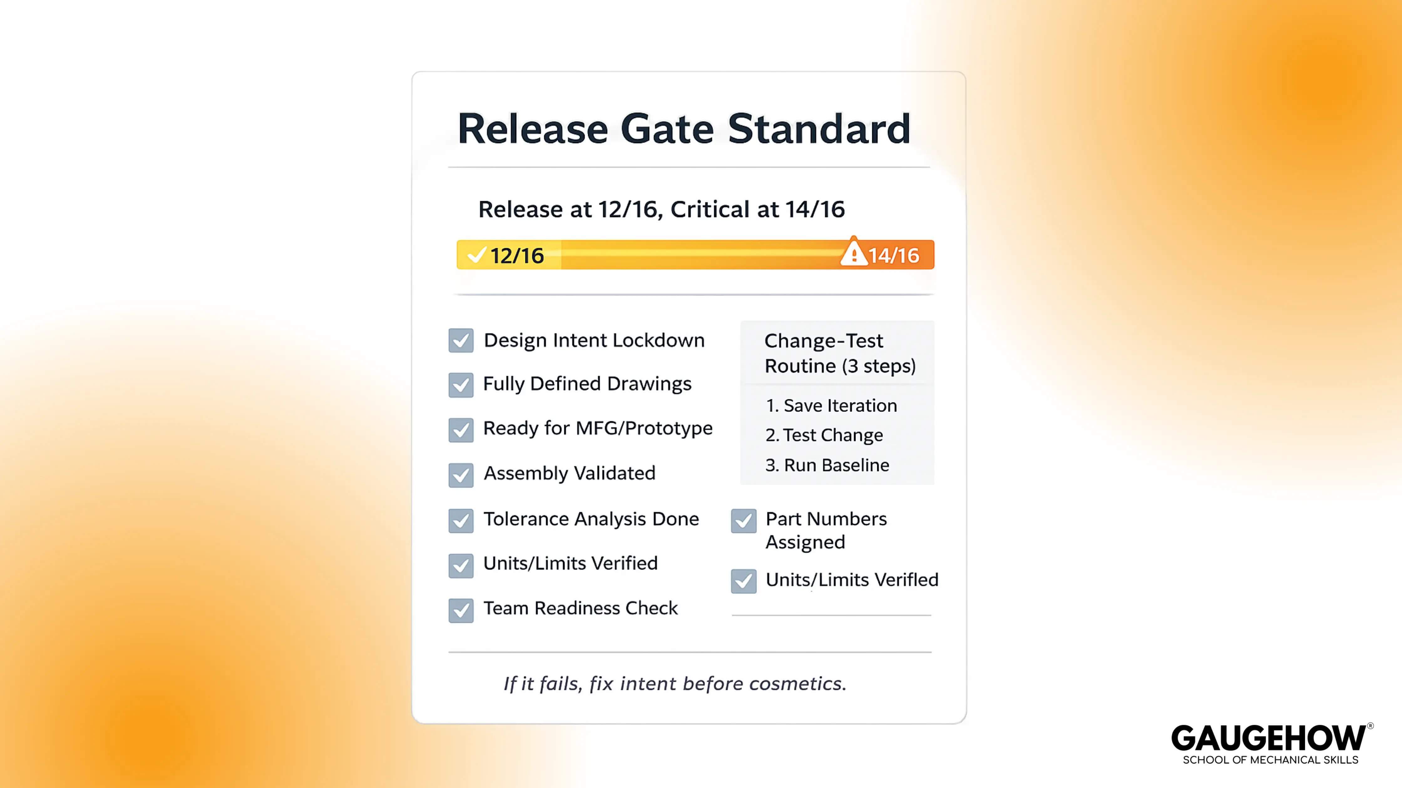
Release Gate Standard: A CAD file is allowed into manufacturing handoff only if it scores 12/16 on the Release Gate, and 14/16 for critical parts, after passing the Change-Test Routine.
That matters because a repeatable gate prevents silent failure. It catches weak references, unclear drawings, and unit mistakes before they become production delays. It also gives you a measurable way to improve your CAD quality over time.
Release Thresholds
Gate Item | Pass Standard | Score |
Sketch Constraints | 0 under-defined sketches on critical features | 0–2 |
Reference Stability | Datums and stable faces drive features | 0–2 |
Rebuild Under Change | Key dimensions can shift 20 percent safely | 0–2 |
Drawing Completeness | Datums, critical dimensions, and notes present | 0–2 |
Assembly Definition | Functional mates, no accidental degrees of freedom | 0–2 |
Export Readiness | STEP or STL opens correctly with the correct units | 0–2 |
Model Tree Hygiene | Meaningful names, clean feature grouping | 0–2 |
Revision Safety | No fragile edge chaining on critical intent | 0–2 |
Change-Test Routine
Change one key dimension by 20 percent, rebuild, and confirm no errors.
Regenerate the drawing and recheck the critical dimensions and datums.
Export the required file and verify units by measuring one known feature.
FAQ
1. Is CAD hard to learn for beginners?
It feels hard if you treat it like drawing. Start with constraints, datums, and sketches, then model one simple part and change a key dimension. If the model rebuilds cleanly, you’re learning the right habits.
2. How long does it take to learn CAD?
Most learners reach basic 2D drafting in 1–2 weeks of consistent practice. For job-ready 3D parametric parts, assemblies, and drawings, expect 6–12 weeks, because you must build change-safe modeling habits, not just commands.
3. What is the difference between 2D CAD and 3D CAD?
2D CAD produces drawings for documentation. 3D CAD builds parametric models and assemblies you can check for fit, motion, and interference, then generates drawings from the model. If you need packaging and revision control, 3D is usually the default.
4. CAD vs CAM: what’s the difference?
CAD defines the geometry and documentation. CAM turns that definition into manufacturing instructions, like CNC toolpaths. CAD answers what to build; CAM answers how to make it.
5. Which CAD software is best for beginners, and free options?
Pick based on deliverables: AutoCAD-style tools for 2D drawings, SolidWorks or Creo-style tools for parametric mechanical parts, Fusion 360 or Onshape-style tools for cloud collaboration. For free learning, try FreeCAD or LibreCAD, then focus on constraints, datums, and exports.
6. What are STEP and STL files used for?
STEP is a neutral 3D exchange format used to hand off solid geometry between CAD, CAM, and suppliers. STL stores a triangulated surface mesh used mainly for 3D printing. Always verify units after export by measuring one known feature.
7. Is CAD a good career skill for mechanical engineers?
Yes, because CAD sits upstream of analysis, manufacturing, and inspection. In most design roles, you are judged on revision safety, drawing clarity, and clean handoffs, not artistic modeling. Strong CAD fundamentals transfer across tools and industries.
Conclusion
To be honest, CAD gets easier when you stop chasing tools and start shipping deliverables. Constrain the sketch, build from stable datums, then change one key dimension and rebuild before you export.
If you want a structured path, Gaugehow’s CAD course takes you from 2D to 3D to drawings with real projects and review checks, so your models stay revision safe, and your handoffs stay clean.
CAD-CAM-CAE Work Platform
Find or Post CAD, CAM and CAE freelance projects, full-time jobs and Internships.
GaugeHow is the platform built for core engineering work. Whether you need a freelancer for a CAD project, a full-time hire, or an engineering intern,post it here and get matched with the right person.


