BIW Interview Questions and Answers (Joining, Weld & Tolerance)


Deepak S Choudhary
Learn More in This Video
Subscribe to GaugeHow for More
Body in White interviews test a specific mix: welding and joining process knowledge, fixture and tooling understanding, and tolerance stack-up thinking, often all in the same conversation. Interviewers want to know you can connect a weld process choice to a real dimensional outcome, not just define terms in isolation.
BIW Fundamentals Questions
1. What does BIW mean, and what does it include?
BIW, or Body in White, refers to the welded and joined sheet metal structure of a vehicle before paint, trim, and other components are added. It typically includes the underbody, side frames, roof, and closures like doors and hoods.
It's called "white" because it's often left in bare, unpainted metal at this stage of production. BIW is a critical checkpoint since it establishes the vehicle's structural and dimensional foundation.
2. Why is dimensional accuracy so critical at the BIW stage?
Every downstream component, from doors to glass to trim, depends on the BIW structure being dimensionally accurate and consistent. Errors at this stage are far more expensive to catch and fix later, once paint and other parts are already attached.
Poor BIW accuracy commonly shows up as panel gap inconsistencies or misaligned closures. This is why BIW dimensional control gets significant engineering and inspection attention.
3. What is the difference between BIW and the trimmed body?
BIW refers to the bare welded structure before paint, glass, interior trim, and other components are installed. The trimmed body refers to the vehicle after paint and trim installation, closer to its final assembled state.
Quality issues traced back to BIW can still be visible in the trimmed body, which is why root cause tracing often goes back to this earlier stage. Understanding this distinction helps clarify where in the process a given defect actually originated.
4. What are the main sheet metal joining methods used in BIW assembly?
Common methods include resistance spot welding, laser welding, structural adhesive bonding, self-piercing rivets, and mechanical clinching. Each method has different strengths, costs, and suitability depending on material type and joint location.
Modern BIW structures often use a mix of these methods rather than relying on just one across the entire vehicle. Material mix, like combining steel and aluminum, is a major factor driving this variety.
5. Why has material mix, like combining steel and aluminum, complicated BIW joining processes?
Different materials often can't use the same joining method effectively, since steel and aluminum have different melting points and electrical properties.
Aluminum resistance spot welding requires different parameters and equipment than steel, and dissimilar metal joints often need adhesive or mechanical fasteners instead.
This has driven wider adoption of multi-material joining strategies within a single vehicle structure. Managing this complexity is a growing and increasingly important skill in modern BIW engineering.
Welding and Joining Processes Questions
6. How does resistance spot welding work, and why is it the dominant BIW joining method?
Resistance spot welding passes high current through two overlapping metal sheets, generating localized heat at the interface that melts and fuses the metal together.
It's fast, doesn't require filler material, and is well suited to high-volume automotive production. Weld quality depends heavily on current, pressure, and time being properly controlled and consistent. It remains the dominant method for steel BIW structures due to this speed and reliability.
7. What is weld nugget size, and why is it a key quality measure in spot welding?
Weld nugget size refers to the diameter of the actual fused metal area created during a spot weld, visible when a weld is destructively tested. A nugget that's too small indicates insufficient strength, while proper nugget formation confirms the weld can handle its intended structural load.
Nugget size is typically verified through destructive peel or chisel testing on sample welds. Consistent nugget size across production welds is a core quality control requirement in BIW.
8. What is laser welding, and what advantages does it offer over resistance spot welding?
Laser welding uses a focused, high-energy laser beam to melt and join metal, often producing a continuous seam rather than discrete spot welds.
It allows for narrower flanges since it doesn't require the same electrode access as spot welding, supporting lighter, more compact designs. Laser welds are also generally faster for long seams and can offer improved structural stiffness in certain joint configurations.
The tradeoff is higher equipment cost and tighter fit-up tolerance requirements between parts.
9. What is structural adhesive bonding, and why is it often combined with spot welding?
Structural adhesive bonding uses engineered adhesives to join panels, distributing load across a larger bonded area rather than concentrated weld points.
Combining adhesive with spot welding, sometimes called weld-bonding, improves stiffness, fatigue resistance, and noise and vibration damping compared to welding alone.
Adhesive also helps join dissimilar materials where welding isn't practical, like steel to aluminum. Proper surface preparation and cure time are critical to adhesive bond strength and reliability.
10. What is a self-piercing rivet, and when is it used instead of welding?
A self-piercing rivet mechanically joins two sheets by punching through them and forming a permanent mechanical interlock, without needing to melt the material.
It's commonly used for joining aluminum or dissimilar material combinations where welding isn't practical or produces poor results. It also avoids heat-affected zone issues that can weaken certain aluminum alloys during welding. This makes it a popular choice in increasingly aluminum-intensive BIW structures.
11. What is a heat-affected zone, and why does it matter in BIW welding?
The heat-affected zone is the area surrounding a weld where the material's properties change due to heat exposure, without actually melting. In some aluminum alloys, this zone can become notably weaker than the surrounding base material, creating a potential failure point.
Engineers account for this by controlling weld parameters and sometimes choosing alternative joining methods for heat-sensitive materials. Understanding heat-affected zone behavior is essential when selecting joining methods for advanced high-strength materials.
Fixturing and Tooling Questions
12. What is a BIW fixture, and what role does it play in weld quality?
A BIW fixture holds sheet metal panels in precise position relative to each other during welding or joining operations. It directly controls the final dimensional accuracy of the assembled structure, since even a perfect weld can't fix parts that were mispositioned before joining.
Fixture wear or misalignment is a common root cause of dimensional drift over a production run. Regular fixture maintenance and calibration checks are essential to sustained BIW quality.
13. What is the 3-2-1 locating principle, and how does it apply to BIW fixturing?
The 3-2-1 principle uses six points of contact, three on a primary surface, two on a secondary surface, and one on a tertiary surface, to fully constrain a part's position in space. It ensures a part is located repeatably every time it's placed in the fixture, regardless of the operator.
This principle underlies most fixture and gauge design across BIW and broader automotive manufacturing. Poorly applied locating principles are a common root cause of inconsistent part positioning.
14. What is a check fixture, and how does it differ from a production fixture?
A check fixture is used specifically for inspection, verifying that a part or subassembly's dimensions match specification, rather than for holding parts during production joining.
It typically has additional gauge pins and indicators not present in a production fixture, allowing detailed pass-fail measurement checks. Production fixtures are optimized for cycle time and welding access, while check fixtures are optimized for accurate, repeatable measurement.
Both need to reference the same datum scheme to ensure consistency between production and verification.
15. Why is fixture datum consistency important across an entire BIW production line?
If different fixtures along the line reference different datum schemes, small positioning discrepancies can accumulate into significant dimensional errors by the time a structure is fully assembled. Consistent datums ensure each station builds on a common, agreed reference rather than compounding independent small errors.
This consistency needs to be maintained not just in fixture design but also in downstream inspection and check fixtures. Datum consistency issues are a common and often difficult-to-diagnose source of BIW dimensional problems.
16. How does fixture wear affect BIW quality over time, and how is it managed?
Locating pins and clamps wear from repeated use, gradually shifting how accurately a fixture positions parts compared to when it was new. This can cause a slow dimensional drift in production that isn't obvious from a single part inspection but shows up in trend data over time.
Scheduled fixture maintenance, calibration checks, and statistical monitoring of key characteristics help catch this drift early. Ignoring fixture wear is a common cause of dimensional quality issues that develop gradually rather than appearing suddenly.
Dimensional Tolerance and GD&T Questions
17. Why is GD&T particularly important for BIW sheet metal structures?
Sheet metal parts are prone to natural variation from stamping, forming, and joining processes, making clear, function-based tolerancing essential to control final assembly outcomes. GD&T defines tolerance zones based on actual function, like panel gap or flushness, rather than arbitrary plus-or-minus dimensions.
This helps balance manufacturing feasibility against the tight fit-and-finish expectations customers have for a vehicle's exterior appearance. Poorly applied tolerancing here often shows up as visible panel gap or flushness inconsistencies.
18. What is tolerance stack-up, and why is it a major concern in BIW assembly?
Tolerance stack-up is the cumulative effect of individual part and joint tolerances combining across a multi-part assembly, potentially exceeding acceptable limits even if each individual part is within its own tolerance.
BIW structures involve many welded and joined parts, making stack-up analysis essential to predicting final dimensional outcomes. Engineers use stack-up analysis during design to identify which tolerances need tightening versus which have enough margin.
Skipping this analysis is a common reason a design that looks fine on paper struggles to meet final assembly targets.
19. What is panel gap and flushness, and how are they controlled in BIW?
Panel gap refers to the space between adjacent body panels, like between a door and the surrounding body opening, while flushness refers to how evenly aligned their surfaces are.
Both are visible quality characteristics that customers notice immediately, making them high-priority dimensional targets. They're controlled through a combination of part tolerance, fixture accuracy, and final assembly adjustment processes.
Consistent panel gap and flushness across a vehicle line is often used as a visible proxy for overall BIW dimensional health.
20. What is a datum reference frame, and why must it be consistent from design through inspection?
A datum reference frame establishes the theoretical reference points a part's geometry is measured against, and it needs to match exactly between the design intent, the manufacturing fixture, and the inspection process.
If the datum scheme used to measure a part doesn't match the one used to build it, measurement results can be misleading or inconsistent. This consistency requirement runs through the entire BIW process, not just individual part drawings.
Datum reference frame mismatches are a frequent and often subtle source of dimensional disputes between design, manufacturing, and quality teams.
21. How does material springback affect dimensional accuracy in BIW stamped parts?
Springback is the tendency of formed sheet metal to partially return toward its original shape after the forming tool is removed, causing the final part to deviate slightly from the intended geometry.
Higher strength materials generally show more springback, making it a growing challenge as automakers use more advanced high-strength steel and aluminum. Engineers compensate by adjusting tool geometry to account for expected springback before the part is even stamped.
Unaccounted springback is a common root cause of dimensional issues traced back to the stamping process rather than BIW joining itself.
Quality and Inspection Questions
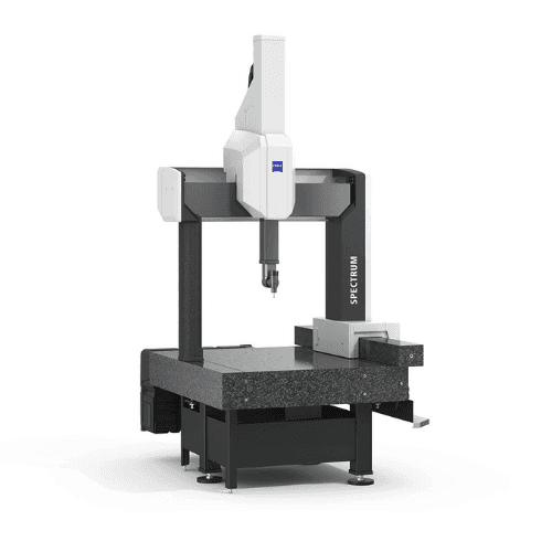
22. What is a Coordinate Measuring Machine (CMM), and how is it used in BIW quality verification?
A CMM uses a precision probe to capture exact coordinate points on a part or assembly, which are then compared against the design's GD&T requirements. It's commonly used for detailed dimensional verification of BIW structures, especially during launch and periodic production audits.
CMM data can pinpoint exactly where and how much a structure deviates from nominal, supporting root cause investigation. It's typically slower than in-line gauging but provides more detailed and flexible measurement capability.
23. What is in-line gauging, and how does it differ from CMM inspection?
In-line gauging uses fixed or automated sensors integrated directly into the production line to check key dimensional characteristics on every part or a high sampling rate.
It provides much faster feedback than CMM inspection, which typically samples parts periodically rather than checking every single one. In-line gauging is well suited to catching sudden process shifts quickly, while CMM inspection provides deeper diagnostic detail when a problem needs root cause investigation.
Most BIW quality strategies use both methods together rather than relying on just one.
24. What is destructive weld testing, and why is it still used alongside non-destructive methods?
Destructive weld testing involves physically breaking or chiseling apart a sample weld to directly measure nugget size and verify weld strength.
Non-destructive methods, like ultrasonic testing, can check welds without damaging them but sometimes can't detect certain defect types as reliably as physical testing.
Destructive testing on periodic samples remains a standard, trusted verification method precisely because it directly confirms actual weld strength. Most BIW weld quality programs combine both approaches for a complete verification strategy.
25. What is Statistical Process Control (SPC), and how is it applied to BIW dimensional quality?
SPC uses control charts to track key dimensional characteristics over time, distinguishing normal process variation from signals that something has actually changed.
In BIW, this might track panel gap, flushness, or a critical hole position across a production run to catch drift before it produces visibly defective parts. It shifts quality monitoring from purely reactive inspection to proactive process management.
Consistent SPC monitoring is a core part of maintaining stable dimensional quality over a long production run.
Advanced and Scenario-Based Questions
26. A door consistently shows a panel gap issue on one side of the vehicle but not the other. How would you investigate?
I'd first check whether the fixture locating that specific side has drifted or shows signs of wear, since asymmetric issues often point to a specific fixture rather than a design problem.
I'd also compare CMM data for that side's components against the design nominal to rule out a stamped part quality issue. I'd review whether the same operator or shift consistently produces the issue, which could point to a process rather than equipment cause.
This kind of one-sided pattern usually narrows the root cause faster than a symmetric, both-sides issue would.
27. How would you approach validating a new weld process for a dissimilar material joint, like steel to aluminum?
I'd start by reviewing published joining guidance and prior validated processes for that specific material combination, since dissimilar joints often require adhesive or mechanical methods rather than direct welding.
I'd run destructive and non-destructive testing on trial samples to confirm joint strength meets requirements under expected load conditions. I'd also evaluate long-term durability concerns, like galvanic corrosion risk between dissimilar metals at the joint interface.
Full validation would include both static strength testing and environmental or fatigue testing before approving the process for production.
28. How would you decide whether a dimensional deviation found during BIW inspection needs immediate correction or can be tracked for now?
I'd weigh how close the deviation is to affecting downstream fit, function, or appearance, since a deviation with real margin remaining may not need immediate escalation.
I'd also consider whether it's an isolated occurrence or part of a trend showing gradual drift, since a trend suggests an underlying cause that will only get worse.
Customer-visible characteristics, like panel gap, generally warrant faster action than internal, non-visible dimensions with the same numeric deviation. This judgment call should always be documented, since it directly affects downstream teams relying on that BIW structure being within spec.
29. Where do you see BIW joining and quality processes evolving with more advanced materials and automation?
Expect continued growth in multi-material joining strategies as automakers push for lighter structures combining steel, aluminum, and composites.
Automated in-line inspection using vision systems and advanced sensors is increasingly replacing manual and periodic sampling-based checks. Digital tools linking CAD tolerance analysis directly to fixture and gauge design are reducing the gap between design intent and actual production accuracy.
Engineers who build strong skills in tools like CATIA V5 alongside solid GD&T fundamentals will be well positioned as BIW processes keep advancing.
FAQ
Do I need hands-on welding experience for a BIW quality engineering role?
Not always, but understanding weld process fundamentals well enough to interpret quality data and root cause issues is essential. Hands-on experience helps, but conceptual understanding paired with strong measurement and tolerance knowledge often matters more.
Is GD&T knowledge as important for BIW roles as it is for machined component roles?
Yes, arguably even more so, since sheet metal's natural variation makes function-based tolerancing critical to controlling visible fit and finish. A solid foundation through a GD&T and Engineering Graphics course directly supports BIW dimensional work.
What's the most common mistake candidates make in BIW interviews?
Describing welding, fixturing, and tolerance as separate topics instead of explaining how they connect to produce a final dimensional outcome. Interviewers specifically look for this connected, systems-level understanding.
How important is CAD software experience for BIW-related roles?
Very important, since most BIW design and tolerance analysis work happens directly in CAD platforms like CATIA. Practical experience through a course like CATIA V5 is a genuinely valuable addition to a BIW-focused resume.
Should I mention specific vehicle programs or material combinations I've worked with in interviews?
Yes, specific examples of materials, joining methods, or dimensional issues you've actually worked through are far more convincing than general statements. It gives interviewers a natural way to dig deeper into your real experience.
Conclusion
BIW interviews reward candidates who can connect joining process choices, fixture design, and dimensional tolerance thinking into one coherent picture, rather than treating each as a separate topic. Use these 30 questions to build the kind of practical, cross-functional understanding that shows up in real production and quality decisions.
If you're building your BIW and CAD foundation from scratch, GaugeHow's free course is a good starting point before moving into more specialized tolerance or metrology training.