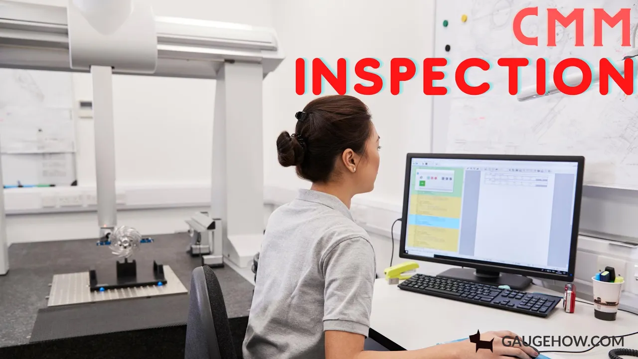
CMM Programming Interview Questions and Answers (PC-DMIS)


Deepak S Choudhary
Learn More in This Video
Subscribe to GaugeHow for More
If you're interviewing for a quality engineer, metrology technician, or CMM programmer role, PC-DMIS will almost certainly come up it's the software running on most Hexagon CMMs and a large share of retrofitted machines across the industry.
Interviewers use it as a quick filter: if you can talk through alignments, feature construction, and GD&T evaluation in PC-DMIS specifically, you've clearly touched a real machine, not just a textbook.
CMM & Metrology Fundamentals
1. What is a CMM and what does it actually measure?
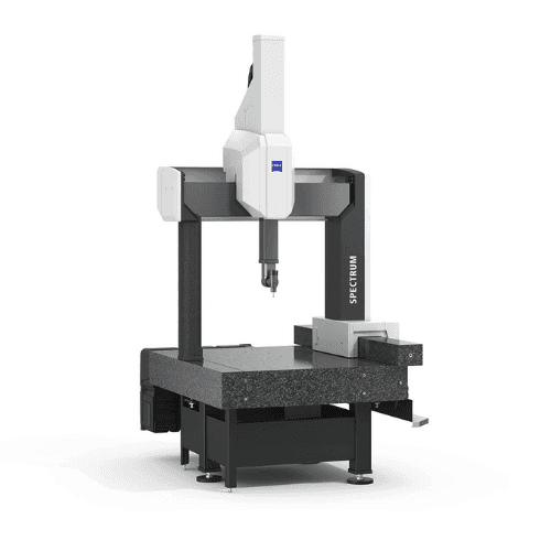
A Coordinate Measuring Machine (CMM) is a device that measures the physical geometry of a part by recording precise X, Y, Z coordinates of points on its surface using a probe.
Those points are then compared against the CAD model or drawing dimensions to check if the part is within tolerance. CMMs are used because they measure far more accurately and repeatably than manual tools like calipers or height gauges.
2. What's the difference between a manual CMM and a DCC (Direct Computer Controlled) CMM?
A manual CMM requires an operator to physically move the probe by hand to each measurement point. A DCC CMM is motor-driven and follows a pre-written program automatically, moving the probe along a defined path without operator intervention. PC-DMIS is used to program both, but DCC machines are what most people mean when they say "automated CMM inspection."
3. What types of probes are commonly used on a CMM, and when would you choose each?
Touch-trigger probes register a single point on contact and are the default for most prismatic parts. Scanning probes stay in continuous contact and collect thousands of points along a surface, used for complex contours like sheet metal or airfoils.
Vision and laser probes are used for non-contact measurement, useful on soft, delicate, or reflective parts that touch probes could damage.
4. Why do CMMs need to be qualified or calibrated regularly, and what does "qualifying a probe" mean?
Machine and environmental factors (temperature, vibration, probe wear) can introduce small errors over time, so calibration ensures measurement accuracy stays traceable to a known standard.
"Qualifying a probe" specifically means measuring a certified reference sphere so the software calculates the exact probe tip diameter and offset before any real measurement begins. Skipping this step means every subsequent measurement carries an unknown, uncorrected error.
5. What's the difference between accuracy and repeatability in a CMM measurement context?
Accuracy is how close a measured value is to the true, correct value. Repeatability is how consistent the CMM is when measuring the same feature multiple times, regardless of whether that consistent value is actually correct.
A CMM can be highly repeatable but inaccurate if it's out of calibration which is exactly why regular qualification matters.
PC-DMIS Programming Basics
6. What are the two main ways to create a measurement routine in PC-DMIS?
You can program online, where the CMM physically moves and takes real points as you build the routine step by step, or offline, where the routine is built against a CAD model on a separate PC without touching the machine at all.
Most production shops favor offline programming because it keeps the CMM free to keep measuring parts while new routines are developed.
7. What is the difference between PC-DMIS Pro and PC-DMIS CAD?
PC-DMIS Pro is the full-featured software without CAD import, meaning routines are built by physically probing points and constructing features from those measured points.
PC-DMIS CAD adds the ability to import a 3D model and build routines by selecting geometry directly on that model, which is faster and reduces programming errors. The underlying measurement and reporting capability is otherwise the same.
8. In PC-DMIS, what is the practical difference between a "feature" and a "dimension"?
A feature is a measured geometric element a circle, plane, line, or cylinder built from a set of probed points.
A dimension is an evaluation applied to that feature, like its diameter, position, or flatness against a tolerance. In short: features describe what was measured, dimensions describe whether it passed or failed.
9. What is a "Path Line" or "Auto Insert" used for in PC-DMIS programming?
They control how the probe moves between measurement points and features, inserting clearance moves so the probe doesn't crash into the part or fixture on its way to the next point.
Auto Insert automatically generates these clearance moves based on part geometry, saving a programmer from manually defining every intermediate move. Getting this wrong is one of the most common causes of probe crashes on new programs.
10. Why would a programmer use "Execute" in a different mode, like DCC vs Manual mode, while testing a new routine?
Manual mode lets the programmer step through the routine slowly and confirm probe paths and measurement points are correct before trusting the machine to run unattended.
Once verified, DCC mode runs the full program automatically at production speed. Testing in manual mode first is a standard safety step to catch collisions before they happen at full speed.
Alignments & Datums
11. What is a part alignment in PC-DMIS, and why is it done before any real measurement?
An alignment establishes the part coordinate system where the part's X, Y, Z origin and orientation sit relative to the CMM's own machine coordinates.
Without it, every measured point would be reported in arbitrary machine coordinates instead of coordinates that match the drawing. It's always the first real step in any measurement routine.
12. What is the 3-2-1 alignment method, and why is it called that?
It's named for the number of points used to constrain each plane: 3 points establish the primary plane (controlling tilt), 2 points establish a secondary line (controlling rotation), and 1 point establishes the origin along the remaining axis.
Together these three steps fully constrain the part in space, matching exactly how GD&T primary, secondary, and tertiary datums work.
13. How would you set up an alignment for a round part that has no obvious flat reference face?
You'd typically use a cylindrical or conical feature's axis as one of the alignment origins instead of a flat plane, often combined with a face perpendicular to that axis for the primary plane.
This mirrors how the part actually gets located in its real assembly or fixture, which is the guiding principle behind choosing any alignment strategy.
14. A part measures fine in one orientation but fails when the CMM operator reloads and re-measures it. What's the likely cause?
The alignment was probably not fully repeatable if it relied on inconsistent points (like grabbing a rough casting surface) rather than stable, well-defined datum features, small differences in part placement shift the entire coordinate system.
Reviewing which features drive the alignment, and tightening how those points are selected, usually resolves it.
15. What's the difference between an alignment and a "temporary" or "iterative" alignment in PC-DMIS?
A standard alignment is set once and used for the rest of the routine. A temporary or iterative alignment is a secondary, refined alignment built during the routine itself often used when an initial rough alignment needs to be corrected using more precise features found only after some points are already taken.
It's common on castings or parts with two levels of reference: rough locating features and precision-machined ones.
Feature Measurement, Probing & GD&T
16. How many points minimum are needed to construct a circle feature in PC-DMIS, and why would you use more?
Mathematically, three points define a circle. In practice, programmers typically take 4 to 6 points (or more for scanning) to average out probe and surface noise, and to catch out-of-round conditions that three points alone could miss. More points generally means a more statistically reliable feature, at the cost of cycle time.
17. What happens if you construct a plane feature using points that are nearly collinear or too close together?
The plane's calculated orientation becomes unstable and highly sensitive to tiny measurement noise, since the math needs points spread well apart to reliably calculate a flat surface's tilt.
PC-DMIS may still construct the feature, but the resulting normal vector can be inaccurate, which then throws off any alignment or dimension built from it.
18. How does PC-DMIS evaluate a GD&T position tolerance callout?
PC-DMIS calculates the deviation of the measured feature's actual center from its true, basic-dimension location, then compares that deviation against the tolerance zone defined in the feature control frame applying bonus tolerance automatically if an MMC or LMC modifier is specified.
The output shows both the calculated position value and a pass/fail against the stated tolerance.
19. A hole measures within its size tolerance but still fails its position callout in PC-DMIS. How do you explain that to someone unfamiliar with GD&T?
Size tolerance only checks how big the hole is, while position tolerance checks how accurately it's located relative to the datums the hole can be exactly the right diameter but still be drilled in the wrong spot.
These are independent checks in GD&T by design, and PC-DMIS evaluates them as two separate dimensions from the same measured feature.
20. What's the difference between measuring a feature with touch points versus a scan in PC-DMIS, in terms of GD&T evaluation quality?
Touch points sample a limited number of discrete locations, which can miss localized defects between points.
A scan collects a dense, continuous stream of points across the surface, giving a much more complete picture for form controls like flatness or profile, which specifically depend on catching variation across the whole surface, not just a few spots.
21. Why might a programmer deliberately measure more points than the drawing technically requires on a critical feature?
Critical or safety-related features (common in aerospace) often get extra points specifically to build statistical confidence in the result and to catch localized defects that a minimal point count could miss entirely. It trades a small amount of cycle time for much stronger evidence that the feature is genuinely in tolerance, not just passing on a lucky sample.
CAD & Offline Programming
22. What's the main advantage of building a PC-DMIS routine offline against a CAD model instead of programming live on the machine?
The CMM stays free to keep measuring other parts while the new routine is developed on a separate PC, which is a major throughput gain in busy shops. It also lets the programmer visually verify probe paths and catch potential collisions in simulation before ever touching the real machine.
23. How does PC-DMIS CAD help prevent probe crashes before a routine ever runs on the real machine?
It simulates the probe's physical path against the imported CAD geometry, including the probe holder and stylus dimensions, and flags where the simulated path would intersect the part or fixture.
Catching this in simulation avoids an expensive real-world collision that can damage the probe or the CMM itself.
24. A CAD model imported into PC-DMIS doesn't quite match the physical part being measured. What's your troubleshooting approach?
First confirm the CAD revision matches the actual part revision, since a common cause is simply measuring against an outdated model. If revisions match, check for units mismatch (inches vs millimeters) or an incorrect CAD import scale, both of which can silently shift every measured comparison.
25. Why would a shop choose to still program partially online even when they have full CAD-based offline capability?
Some real-world conditions like a part that deviates significantly from nominal CAD due to a casting or forming process are easier to handle by verifying and adjusting points live on the actual part rather than trusting a theoretical CAD-based path blindly.
Offline programming gets you most of the way there quickly, but final verification on the real part is still common practice.
Reporting, Automation & Troubleshooting
26. A PC-DMIS routine runs successfully but the final report shows a dimension as blank instead of a value. What do you check first?
This usually means the dimension is referencing a feature that either failed to construct or wasn't actually measured in that run check the feature tree for a missing or failed feature above the dimension in question.
It's rarely a reporting bug; it's almost always an upstream feature problem.
27. How would you set up PC-DMIS to automatically flag a part as failed and alert someone without a person watching the screen?
You'd configure the routine's dimension tolerances so out-of-tolerance results are visually flagged, then connect that output to an SPC system or Hexagon's cloud-based notification tools, which can push mobile or email alerts when a part fails. This is standard for unattended, high-volume inspection cells.
28. What is SPC (Statistical Process Control) connectivity used for in a PC-DMIS workflow, and why does it matter beyond a single part's pass/fail?
SPC connectivity routes measurement results into a statistical system that tracks trends across many parts over time, which can reveal a process drifting out of control before individual parts actually start failing. A single part passing tells you almost nothing about the process; SPC trend data tells you whether the process itself is stable.
29. You're asked to make one PC-DMIS routine measure 10 identical parts loaded on a fixture without manually running it 10 times. What feature would you use?
This calls for part program looping combined with an alignment that repeats per fixture position often built using a loop construct or an array of alignments corresponding to each fixture slot.
Automating this avoids manually re-triggering the same routine and reduces operator error across repetitive production runs.
30. During an interview, you're asked to walk through your general troubleshooting order when a PC-DMIS routine gives an unexpected fail. What's a clear, structured answer?
Start by confirming the alignment is correct and repeatable, since a bad alignment throws off every downstream measurement. Next, check whether the specific feature that failed was actually constructed from valid points, not a partial or noisy measurement.
Finally, confirm the tolerance and any GD&T modifiers in the dimension itself match what's actually on the drawing, since a typo in the tolerance setup is a surprisingly common root cause.
Frequently Asked Questions
Do I need to know PC-DMIS scripting or its Basic language for an entry-level CMM programming interview?
For most entry-level roles, understanding the graphical programming workflow alignments, features, dimensions matters more than scripting. Basic scripting knowledge becomes more relevant for automation-heavy or senior programming roles, so it's worth mentioning if you have it, but not a hard requirement for freshers.
Is it okay to say "I've only used PC-DMIS in training, not in a live production environment" in an interview?
Yes, being honest about this is far better than pretending otherwise, since interviewers can tell quickly through follow-up questions. Pair that honesty with specifics what alignments and features you practiced with to show the training was hands-on, not just theoretical.
How different is PC-DMIS from other CMM software like CALYPSO in terms of interview questions?
The core concepts alignments, GD&T evaluation, feature construction transfer across almost any CMM software, since they're metrology fundamentals, not PC-DMIS-specific quirks.
Interviewers mentioning PC-DMIS by name are usually just confirming you've used their specific tool, not testing a completely different skill set.
What's the single most common mistake candidates make in a CMM programming interview?
Describing measurement steps without mentioning alignment first jumping straight to "I measured the hole's position" without explaining what coordinate system that position was measured against.
Since almost every real measurement depends on a correct alignment, skipping it in your explanation is an easy tell that experience is thin.
Conclusion
CMM programming interviews built around PC-DMIS almost always trace back to the same core sequence: qualify the probe, build a correct alignment, construct clean features, then evaluate dimensions and GD&T against those features.
If you can walk through that sequence confidently, and explain what goes wrong at each stage, you'll handle the vast majority of questions an interviewer throws at you, PC-DMIS-specific or not.
To build this hands-on, GaugeHow's Engineering Metrology & 3D Measurement course covers CMM fundamentals, probing, and alignments from the ground up. Since so much of CMM evaluation is really GD&T applied in software, pair it with the GD&T and Engineering Graphics course and if your role also touches part programming upstream of inspection, the CNC Programming course rounds out the full make-and-measure workflow.