Reverse Engineering Interview Questions and Answers (3D Scan to CAD)


Deepak S Choudhary
Learn More in This Video
Subscribe to GaugeHow for More
Reverse engineering interviews especially for roles involving 3D scan-to-CAD work tend to focus on whether you actually understand the journey from a raw scanned point cloud to a clean, usable CAD model, not just whether you can name the software involved.
If you're a student or fresher preparing for a reverse engineering, metrology, or 3D scanning role, this guide covers 30 commonly asked questions ,so you can revise quickly and explain concepts confidently in your own words, whether the interviewer asks about scanning hardware, mesh cleanup, or surface fitting in CAD.
Basic Concepts
1. What is reverse engineering in a mechanical design context?
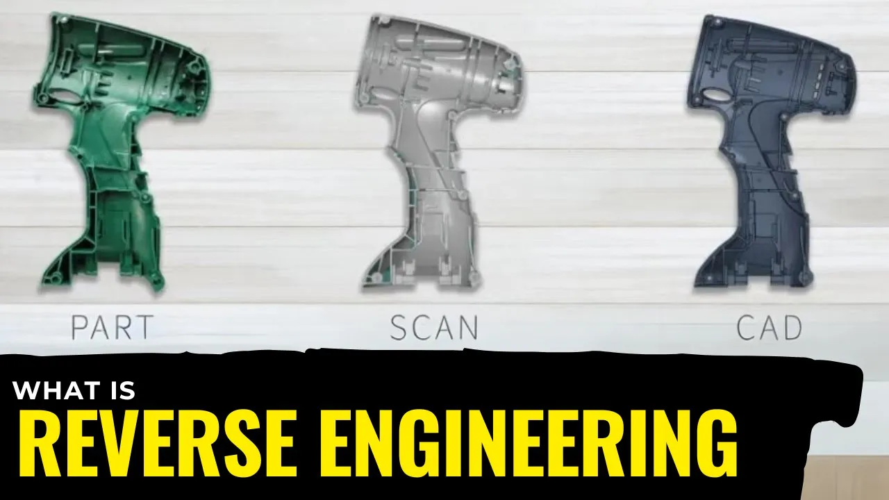
Reverse engineering is the process of recreating a digital CAD model from an existing physical part, usually by scanning it and converting the scan data into usable geometry. It's used when original design files are missing, outdated, or need modification. The goal is a model accurate enough to manufacture, modify, or inspect against.
2. What is the general workflow from 3D scan to finished CAD model?
The typical workflow starts with scanning the part to capture point cloud data, followed by mesh cleanup, then surface or solid model creation in CAD, and finally accuracy verification against the original part.
Each stage depends on the quality of the one before it. Skipping cleanup steps almost always causes problems later in the CAD stage.
3. What is a point cloud?
A point cloud is a large set of XYZ coordinate points captured by a 3D scanner, representing the surface of a physical object. It's the raw data output before any processing or modeling happens. On its own, a point cloud has no surface information, just discrete points in space.
4. What is the difference between a point cloud and a mesh?
A point cloud is just a collection of individual points with no connectivity between them. A mesh connects those points into triangles to form a continuous surface representation. Meshing is usually the first major processing step after raw scanning.
5. What types of 3D scanners are commonly used in reverse engineering?
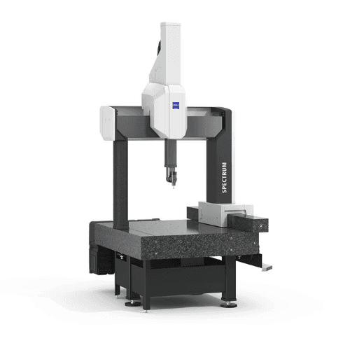
Common types include structured light scanners, laser scanners, and contact-based coordinate measuring machines (CMMs). Structured light scanners are popular for their speed and accuracy on small to medium parts. The right scanner depends on part size, surface finish, and required accuracy.
6. What is the difference between contact and non-contact scanning?
Contact scanning, like a CMM with a touch probe, physically touches the part to record points one at a time, offering very high accuracy but slower data capture. Non-contact scanning, like laser or structured light, captures thousands of points per second without touching the surface. Non-contact methods are generally faster but can struggle with reflective or transparent surfaces.
7. Why might a scanned surface have gaps or missing data?
Gaps often occur on reflective, dark, or transparent surfaces that scatter or absorb the scanner's light inconsistently. Deep pockets, undercuts, or steep angles relative to the scanner can also block line of sight. Applying a matte scanning spray or repositioning the part often resolves these issues.
8. What is STL format, and why is it commonly used in reverse engineering?
STL is a standard mesh file format that represents a 3D surface as a network of triangles, widely supported across scanning and CAD software. It's commonly used as an intermediate format between scan processing and CAD modeling. STL files don't carry color, material, or precise curve data, only geometry.
Scan Data Processing
9. What is mesh cleanup, and why is it necessary?
Mesh cleanup involves removing noise, filling small holes, and fixing errors like overlapping or inverted triangles in the scanned mesh data. Raw scan data is rarely clean enough to model directly. Skipping this step usually causes errors or inaccurate surfaces later in CAD.
10. What is noise in scan data, and how is it removed?
Noise refers to random, inaccurate points captured during scanning due to sensor limitations, vibration, or reflective surfaces. It's typically removed using smoothing or filtering tools in scan processing software before meshing. Excessive noise reduction can also unintentionally remove real surface detail if not done carefully.
11. What is mesh decimation, and when would you use it?
Mesh decimation reduces the number of triangles in a mesh while preserving its overall shape, making the file smaller and easier to work with. It's useful when a scan has unnecessarily high resolution for the modeling task at hand. Over-decimating can lose important surface detail, so it needs to be applied carefully.
12. What is alignment in the context of multiple scans?
Alignment is the process of merging multiple scans taken from different angles into a single, unified coordinate system. It's necessary because a single scan rarely captures an entire complex part. Common alignment methods include best-fit alignment and reference point alignment using markers.
13. What are scanning targets or markers, and why are they used?
Targets are small reflective or printed markers placed on or around a part before scanning, used as reference points to align multiple scans accurately.
They're especially useful for large or complex parts requiring scans from many angles. Without targets, alignment relies purely on surface geometry matching, which can be less reliable on simple or symmetric shapes.
14. What is mesh repair, and what kind of issues does it fix?
Mesh repair fixes problems like holes, non-manifold edges, intersecting triangles, and inconsistent normals in a scanned mesh. These issues, if left uncorrected, can prevent successful surface fitting or solid model creation later.
Most scan processing software includes automated repair tools alongside manual editing options.
15. What is the difference between mesh-based and parametric reverse engineering?
Mesh-based reverse engineering keeps the final model as a triangulated surface without editable design history. Parametric reverse engineering recreates the part using standard CAD features like extrudes, fillets, and sketches that can be edited later. Parametric models are generally preferred when the part needs future design changes.
16. How do you handle scan data for a part with both freeform and prismatic features?
Freeform areas like organic curves are typically modeled directly from the mesh as surfaces, while prismatic features like holes, bosses, and flat faces are usually rebuilt as parametric features. This hybrid approach gives flexibility where needed while keeping critical features editable. It's one of the more common real-world scenarios in reverse engineering work.
CAD Modeling and Accuracy
17. What is surface fitting, and why is it used in reverse engineering?
Surface fitting is the process of creating smooth, mathematically defined CAD surfaces that closely follow the shape of a scanned mesh. It converts raw triangulated data into usable, editable CAD geometry. Good surface fitting balances accuracy to the scan with smoothness and manufacturability.
18. What CAD software is commonly used for reverse engineering work?
SolidWorks is widely used for converting cleaned mesh data into parametric or surface-based CAD models, often alongside dedicated reverse engineering or scan-processing software for the early mesh stages. Comfort with SolidWorks 2024 for surface and solid modeling is a strong foundation for this kind of role.
19. What is best-fit alignment, and when is it used?
Best-fit alignment automatically positions a scanned mesh to minimize overall deviation from a reference, like an existing CAD model or coordinate system, without relying on specific reference points. It's commonly used when comparing a scanned part to its original design intent. It differs from datum-based alignment, which uses specific functional features instead.
20. How do you verify the accuracy of a reverse-engineered CAD model?
Accuracy is typically verified by comparing the finished CAD model back against the original scan data using a color deviation map, which highlights areas of high or low agreement. Critical dimensions may also be checked manually against the physical part.
This step confirms the model is fit for its intended purpose, whether that's manufacturing or inspection.
21. What is a deviation map, and how is it used?
A deviation map is a color-coded visualization showing how closely a CAD model matches the original scan data, with colors indicating the magnitude of deviation at each point. Green typically indicates close agreement, while red or blue indicate larger positive or negative deviation. It's a standard tool for communicating accuracy results to both engineers and clients.
22. What challenges come up when reverse engineering a part with worn or damaged features?
Worn or damaged areas don't represent the original design intent, so scanning them directly can reproduce the defect rather than the correct geometry. Engineers often need to reconstruct the original feature using symmetry, reference parts, or engineering judgment. This is one of the more difficult judgment calls in reverse engineering work.
23. What is the role of GD&T in reverse engineering for manufacturing?
Once a parametric model is created, GD&T is applied to define functional tolerances needed for the part to work correctly, since scan data alone has no inherent tolerance information. This step bridges the gap between captured geometry and a manufacturable drawing. Without it, a reverse-engineered part might look correct but fail to function or assemble properly.
Troubleshooting and Practical Scenarios
24. A scanned mesh has several small holes after processing. What would you do?
Most scan processing software includes automatic hole-filling tools that work well for small, simple gaps. For larger or more complex holes, manual patching using surrounding surface curvature as a guide gives better results. The original scan should also be reviewed to see if a quick rescan of that area is a better fix.
25. The final CAD model doesn't match the part within acceptable tolerance. What's your troubleshooting approach?
Start by checking the deviation map to identify exactly where the largest errors occur, rather than assuming the whole model is off.
Then review whether those areas correspond to known scanning issues like reflective surfaces or alignment errors. Often the issue traces back to the scan data itself rather than the CAD modeling step.
26. A scan of a symmetric part shows unexpected asymmetry. What might be causing this?
This is often caused by partial scan coverage, where one side wasn't captured as completely as the other, or by alignment drift across multiple scan passes. It can also genuinely reflect manufacturing variation in the physical part itself. Comparing scan coverage and revisiting alignment usually clarifies which it is.
27. You're asked to reverse engineer a part for manufacturing, but the original had visible wear on a critical surface. How would you approach it?
You'd avoid directly copying the worn geometry and instead reconstruct the intended surface using symmetry, mating part geometry, or design reasoning about the part's function.
Where possible, comparing against a less-worn reference part of the same design helps validate the reconstruction. This requires engineering judgment beyond what the scan data alone can provide.
28. A client wants an editable, parametric CAD model, but the part has complex freeform surfaces. How would you handle this?
You'd use a hybrid modeling approach, applying parametric features to flat, prismatic, or functional areas while using surface fitting for the complex freeform regions.
This gives the client editability where it matters most without forcing unrealistic parametric definitions onto organic shapes. Setting this expectation with the client early avoids confusion later.
29. Scan alignment between two passes keeps failing or producing high error. What would you check?
Check whether there's enough overlapping geometry or shared reference targets between the two scans for the alignment algorithm to work with. Featureless or highly symmetric overlap regions are a common cause of alignment failure. Adding reference targets or rescanning with more overlap usually resolves it.
30. What's the most common mistake students or new reverse engineering professionals make?
The most common mistake is jumping straight into CAD modeling without first properly cleaning and validating the mesh data, which carries errors forward into the final model. A close second is treating worn or damaged scan data as if it represents correct design intent without question. Both come from rushing past the data quality checks early in the workflow.
Frequently Asked Questions
Q: Is reverse engineering a good career path for mechanical engineering students?
A: Yes it's a growing specialization across automotive, aerospace, and product design industries, valued wherever original CAD data is missing or parts need to be digitized for redesign or inspection.
Q: Do I need to know how to operate a 3D scanner for an entry-level role?
A: Hands-on scanner experience is a strong advantage, but understanding scanning principles and limitations conceptually is often enough to get started, since many companies provide on-the-job training for specific hardware.
Q: What's the difference between reverse engineering for inspection versus manufacturing?
A: Reverse engineering for inspection usually compares a scan directly against an existing CAD model to check accuracy, while reverse engineering for manufacturing focuses on creating a clean, editable CAD model that can be used to produce new parts.
Q: What CAD skills should I focus on before a reverse engineering interview?
A: Comfort with surface modeling and parametric feature creation in software like SolidWorks is the most valuable skill, since most reverse engineering work eventually lands in standard CAD tools regardless of the scanning hardware used.
Q: How should I structure my answers as a fresher candidate?
A: Keep answers short, specific, and grounded in the actual workflow logic rather than memorized definitions. Interviewers respond better to clear, applied reasoning than to long, recited answers.
Conclusion
Reverse engineering interviews for 3D scan-to-CAD roles consistently come back to a few core ideas: understanding the journey from raw point cloud to clean mesh to usable CAD geometry, knowing how to verify accuracy with tools like deviation maps, and using engineering judgment when scan data doesn't perfectly represent design intent.
If you can explain that workflow clearly and reason through a troubleshooting scenario, you'll be well prepared for almost any question an interviewer asks.
Want to build hands-on experience with this exact workflow? Explore GaugeHow's Computer-Aided Reverse Engineering course.