Aerospace GD&T Interview Questions and Answers


Deepak S Choudhary
Learn More in This Video
Subscribe to GaugeHow for More
GD&T interviews in aerospace tend to separate candidates fast either you can actually read a feature control frame and explain what it's controlling, or you're reciting definitions without real application.
Because aerospace parts mate with tight tolerances across multiple suppliers, interviewers lean hard on whether you understand datums, tolerance zones, and how a drawing callout translates to an actual inspection method.
GD&T Fundamentals Questions
1. What is GD&T, and why is it used instead of plus-or-minus tolerancing?
GD&T, or Geometric Dimensioning and Tolerancing, is a symbolic language used to define and communicate allowable variation in a part's form, orientation, location, and size. Plus-or-minus tolerancing only controls size and location in a limited way and often creates ambiguous or overly restrictive tolerance zones.
GD&T defines tolerance zones based on the part's actual function, which usually allows more manufacturing flexibility without sacrificing fit or performance. This is especially important in aerospace, where parts from different suppliers must mate correctly every time.
2. What standard governs GD&T in the United States, and how does it compare to the international standard?
ASME Y14.5 is the primary GD&T standard used in the United States and is widely adopted across the aerospace industry. ISO GPS is the international equivalent, and while the two standards share most core concepts, there are some differences in symbol usage and interpretation.
Aerospace companies working with international suppliers need to clarify which standard a drawing follows, since assuming the wrong one can lead to inspection disputes. Most U.S. aerospace primes default to ASME Y14.5 unless a contract specifically calls out otherwise.
3. What is a datum, and why is it foundational to GD&T?
A datum is a theoretically exact reference point, line, or plane used to establish the origin for measuring other features on a part. Nearly every geometric tolerance on a drawing references back to one or more datums, which is why selecting the correct datums early in design is critical.
Poorly chosen datums can lead to a part that measures "in tolerance" on paper but doesn't actually function correctly when assembled. Datums are typically chosen based on how the part mates or is held during manufacturing and inspection.
4. What is the difference between a datum feature and a datum feature simulator?
A datum feature is the actual physical feature on the part, like a hole or a flat surface, identified on the drawing as a reference. A datum feature simulator is the physical tooling, like a gauge pin or a surface plate, used to establish the theoretical datum during actual inspection.
The simulator represents the idealized, perfect version of the datum feature since no manufactured surface is perfectly flat or round. Understanding this distinction is essential for correctly interpreting how a part will actually be measured.
5. What is the difference between form, orientation, location, and profile tolerances in GD&T?
Form tolerances, like flatness and straightness, control a single feature's shape without reference to any datum. Orientation tolerances, like perpendicularity and parallelism, control a feature's angle relative to a datum.
Location tolerances, like position and concentricity, control where a feature sits relative to datums. Profile tolerances can control a combination of size, form, orientation, and location simultaneously, making them one of the most versatile and commonly used symbols in aerospace drawings.
6. What is Rule #1, or the envelope principle, in GD&T?
Rule #1 states that a feature of size must not violate its maximum material boundary, meaning the feature's form error is automatically limited by its size tolerance unless otherwise specified. In simple terms, a shaft at its largest allowed diameter must still be perfectly round and straight within that same tolerance.
This rule applies by default unless a drawing specifically calls out an exception, like independency. Misunderstanding Rule #1 is a common source of disagreement between design and inspection teams.
Datums and Tolerance Zones Questions
7. What is a datum reference frame, and how is it established?
A datum reference frame is a set of three mutually perpendicular planes established from a part's chosen datums, used to fully constrain all six degrees of freedom for measurement.
The primary datum typically constrains the most degrees of freedom, followed by the secondary and tertiary datums constraining fewer each. This ordered hierarchy ensures measurements are repeatable regardless of who performs the inspection. Getting the datum order wrong can produce inconsistent measurement results even when everyone is using the same drawing.
8. What is the difference between a primary, secondary, and tertiary datum?
The primary datum typically contacts the datum feature simulator across the largest area and constrains the most degrees of freedom, often three. The secondary datum contacts at fewer points and constrains additional degrees of freedom not already fixed by the primary.
The tertiary datum typically contacts at a single point and constrains the final remaining degree of freedom. Together, all three fully constrain the part's position and orientation for consistent measurement.
9. What is Maximum Material Condition (MMC), and how does it affect a tolerance zone?
MMC refers to the condition where a feature contains the maximum amount of material allowed by its size tolerance, such as the largest allowed shaft diameter or smallest allowed hole diameter. When a position tolerance is specified at MMC, the allowable tolerance zone can actually grow as the feature deviates from MMC toward its least material condition.
This is called bonus tolerance, and it reflects the fact that a smaller hole, for example, has more room to shift position and still assemble correctly. MMC callouts are common in aerospace fastener holes where assembly clearance matters more than absolute position precision.
10. What is Least Material Condition (LMC), and when is it typically used?
LMC refers to the condition where a feature contains the minimum amount of material allowed by its size tolerance, the opposite extreme from MMC. It's typically used when maintaining a minimum wall thickness matters more than assembly clearance, such as ensuring adequate material remains around a hole for structural strength.
Like MMC, LMC callouts can also provide bonus tolerance as the feature deviates from the LMC condition. It's less commonly used than MMC but appears in aerospace drawings where wall thickness is a critical design driver.
11. What is a virtual condition, and why does it matter for functional gauging?
Virtual condition is the worst-case boundary generated by the combined effects of a feature's size limit and its geometric tolerance, used to design functional gauges that verify assembly. It represents the theoretical smallest hole or largest shaft that must still allow proper assembly given both size and position variation.
Functional gauges are built to this virtual condition boundary to give a quick pass-fail check without needing full coordinate measurement. Understanding virtual condition helps engineers predict whether a design will actually assemble before physical parts are even made.
12. What is a floating fastener versus a fixed fastener condition, and how does it affect tolerance calculations?
A floating fastener condition applies when both mating parts have clearance holes and the fastener can float slightly to align them, typically allowing a larger position tolerance.
A fixed fastener condition applies when one part has a threaded hole and the fastener is fixed relative to it, generally requiring a tighter position tolerance since there's less flexibility to compensate for misalignment. Standard formulas exist to calculate the appropriate position tolerance for each condition based on hole and fastener sizes.
Misapplying the wrong formula is a common design error that can lead to assembly issues discovered too late.
Feature Control Frames and Symbols Questions
13. What information is contained in a feature control frame?
A feature control frame contains the geometric characteristic symbol, the tolerance value, any applicable modifiers like MMC, and the datum references in their proper order of precedence.
Reading it left to right tells you exactly what's being controlled, how much variation is allowed, and relative to which datums. Missing or misordered datum references in a feature control frame can completely change how a part is measured.
This is why interviewers often ask candidates to read and interpret a feature control frame directly during an interview.
14. What is the difference between position tolerance and profile of a surface tolerance?
Position tolerance controls the location of a feature of size, like a hole, relative to specified datums, and is typically shown as a cylindrical or spherical tolerance zone.
Profile of a surface tolerance can control the size, form, orientation, and location of a surface simultaneously, offering more comprehensive control in a single callout. Profile tolerance is increasingly popular in aerospace because it can replace multiple separate tolerances with one clearly defined zone.
Choosing between the two often depends on whether the feature is a size feature like a hole, or a surface like a contoured skin panel.
15. What does the symbol for true position mean, and how is it different from a basic dimension?
True position refers to the theoretically exact location of a feature, defined using basic dimensions that carry no tolerance themselves. A basic dimension establishes the exact target location, while the position tolerance in the feature control frame defines how much the actual feature can deviate from that target.
Basic dimensions are typically shown in a box on the drawing to distinguish them from toleranced dimensions. Confusing a basic dimension with a toleranced one is a common misread that can lead to incorrect part acceptance decisions.
16. What is a composite tolerance, and how does it differ from a single-segment feature control frame?
A composite tolerance uses two or more segments within a single feature control frame, typically applying a looser pattern-locating tolerance in the upper segment and a tighter feature-to-feature tolerance in the lower segment.
This allows a hole pattern to have some flexibility in its overall location relative to datums, while still requiring tight spacing consistency between the holes themselves. It's commonly used for bolt patterns where overall alignment matters less than consistent hole-to-hole spacing.
Misreading which segment applies to which requirement is a frequent source of measurement disputes.
17. What is the meaning of the "free state" modifier in GD&T, and when is it used?
The free state modifier indicates that a tolerance applies to a part while it's unconstrained by any external forces, which matters for flexible parts that can distort under their own weight or from prior manufacturing processes.
It's commonly applied to thin-walled or large, flexible aerospace parts like sheet metal skins that don't hold a rigid shape on their own. Without this modifier, ambiguity exists about whether the part should be measured as manufactured or while restrained to its intended assembly shape.
Interviewers may ask this to see if you understand tolerancing challenges specific to flexible, non-rigid aerospace structures.
GD&T Standards and Application Questions
18. Why is GD&T particularly critical in aerospace compared to other industries?
Aerospace parts are frequently manufactured across multiple suppliers and must assemble correctly the first time, since rework or field fit issues are extremely costly and can delay aircraft delivery.
GD&T provides an unambiguous, universally interpretable way to communicate design intent so every supplier measures and manufactures to the same standard. It also directly supports interchangeability, which is essential when spare parts must fit aircraft built years apart.
The cost of a misinterpreted tolerance in aerospace is far higher than in most other manufacturing industries.
19. How does GD&T support interchangeability of aerospace parts across different production lots?
By defining tolerance zones based on function rather than arbitrary plus-or-minus values, GD&T ensures any part within its defined tolerance will fit and function correctly, regardless of which lot or supplier produced it.
This is critical for spare parts and maintenance, repair, and overhaul operations where a replacement part must fit without custom fitting.
Functional gauging designed around virtual condition further supports this by giving a consistent, tool-based pass-fail check. pWithout consistent GD&T application, interchangeability would require case-by-case fitting, which isn't practical at aerospace production volumes.
20. What is a Coordinate Measuring Machine (CMM), and how does it relate to GD&T inspection?
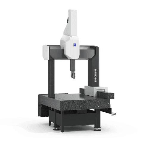
A CMM is a precision measurement tool that uses a probe to capture the exact coordinates of points on a part's surface, which are then used to calculate actual geometric values like position, flatness, or profile.
CMM software can directly evaluate measured data against GD&T callouts, calculating whether a feature falls within its specified tolerance zone.
This has made CMMs the standard inspection method for complex aerospace geometry that would be difficult to check with traditional gauges. Understanding how a CMM interprets a feature control frame helps engineers design tolerances that are actually practical to measure.
21. What is the role of GD&T in reducing scrap and rework in aerospace manufacturing?
Well-applied GD&T defines tolerances based on actual function rather than overly tight, arbitrary values, giving manufacturing more realistic room to produce parts without unnecessary rejection.
It also reduces ambiguity between design intent and inspection interpretation, preventing good parts from being incorrectly rejected due to a misread tolerance.
Bonus tolerance features like MMC can further reduce unnecessary scrap by allowing more variation when a feature is away from its worst-case condition. Poorly applied GD&T, on the other hand, can actually increase scrap by creating unnecessarily tight or ambiguous requirements.
Inspection, Measurement, and Metrology Questions
22. What is measurement uncertainty, and why does it matter when verifying a tight GD&T tolerance?
Measurement uncertainty represents the range of doubt around any measured value, caused by factors like equipment accuracy, environmental conditions, and operator technique.
When a tolerance is very tight, measurement uncertainty can become large enough relative to the tolerance that it's genuinely unclear whether a part passes or fails.
Aerospace inspection processes often require documented uncertainty budgets, especially for critical characteristics with tight GD&T callouts. Ignoring measurement uncertainty can lead to inconsistent accept-reject decisions between different inspectors or labs.
23. What is a functional gauge, and how does it differ from a CMM for verifying GD&T callouts?
A functional gauge is a physical fixture built to a part's virtual condition, giving a fast pass-fail check by simply attempting to fit the part or its features into the gauge.
A CMM instead captures actual numeric measurement data, which takes longer but provides more detailed information about exactly how much a feature deviates and in which direction. Functional gauges are well suited to high-volume production where speed matters more than detailed data.
CMMs are typically preferred for first article inspection or root cause investigation where understanding the exact deviation matters.
24. How do you verify a position tolerance callout that includes an MMC modifier during inspection?
I'd first measure the actual size of the feature, like a hole diameter, and compare it against its MMC and LMC limits to determine how much bonus tolerance applies. I'd then measure the feature's actual position relative to the specified datums using either a CMM or an appropriately designed functional gauge.
Adding the bonus tolerance to the stated position tolerance gives the total allowable position deviation for that specific feature size. This step-by-step approach ensures the bonus tolerance benefit is properly credited rather than rejecting a part that's actually within its allowable zone.
25. What common mistakes do engineers make when specifying GD&T on aerospace drawings?
A frequent mistake is over-tolerancing, applying unnecessarily tight tolerances that increase manufacturing cost without a real functional reason.
Another common issue is selecting datums that don't reflect how the part is actually held or assembled, creating a mismatch between design intent and real-world function. Missing or incorrectly ordered datum references in a feature control frame can also make a callout ambiguous or impossible to properly inspect.
Reviewing tolerances against actual manufacturing and inspection capability early in design helps catch these issues before they reach production.
Advanced and Scenario-Based Questions
26. You receive a part that measures out of position tolerance on a CMM, but it visually fits fine during trial assembly. How would you investigate?
I'd first check whether the position tolerance includes an MMC modifier, since the feature's actual size might qualify it for bonus tolerance not accounted for in the initial CMM evaluation.
I'd also verify the CMM program is using the correct datum reference frame and evaluating the feature against the proper virtual condition. If the callout and setup are both correct, I'd double check the physical assembly wasn't just getting lucky due to clearance elsewhere in the mating parts.
This kind of discrepancy usually points to either a measurement setup error or a legitimate but subtle tolerance calculation being missed.
27. How would you approach applying GD&T to a new sheet metal aerospace bracket for the first time?
I'd start by identifying how the bracket is actually held and located during both manufacturing and final assembly, since that should directly inform datum selection.
Given sheet metal's tendency to distort, I'd consider whether a free state modifier is needed for any critical features. I'd choose profile tolerance where practical, since it can efficiently control multiple characteristics of a formed surface in a single callout.
Finally, I'd review the tolerance scheme with manufacturing and inspection early to confirm it's actually practical to produce and measure, not just theoretically correct.
28. How do you decide between using position tolerance and profile tolerance for a new design?
Position tolerance is typically the better choice for features of size, like holes or pins, where you're controlling location relative to datums. Profile tolerance works better for complex surfaces or contours where you need to control size, form, and location together in one callout.
Profile tolerance has become increasingly popular in aerospace because it often reduces the total number of separate tolerances needed on a drawing. The decision usually comes down to whether you're tolerancing a discrete feature of size or a more complex surface geometry.
29. How would you handle a disagreement with a supplier over how to interpret a GD&T callout on your drawing?
I'd first go back to the drawing itself and confirm exactly what standard, like ASME Y14.5, the callout is meant to follow, since interpretation rules can differ slightly between standards.
I'd walk through the feature control frame systematically with the supplier, confirming datum order and any modifiers together rather than assuming they're reading it the same way I am.
If genuine ambiguity exists in how the drawing is written, I'd treat that as valuable feedback to clarify the drawing for future production, not just resolve the immediate dispute. Clear, collaborative communication usually resolves these disagreements faster than a purely contractual escalation.
30. Where do you see GD&T application evolving with more advanced CAD and metrology tools?
Model-Based Definition is increasingly replacing traditional 2D drawings, embedding GD&T directly into the 3D CAD model as the authoritative source of design intent. This reduces translation errors between design and inspection since CMM and other measurement software can pull tolerance data directly from the model.
Automated inspection systems are also getting better at directly evaluating complex GD&T callouts without manual programming for each feature. Engineers who build strong GD&T fundamentals now, such as through a GD&T and Engineering Graphics course, will adapt faster as these model-based workflows keep expanding.
FAQ
Do I need to memorize every GD&T symbol for an aerospace interview?
You should recognize and understand the most commonly used symbols, like position, profile, flatness, and perpendicularity, well enough to explain their function. Perfect recall of every rarely used symbol matters less than demonstrating you can correctly read and apply the common ones.
Is GD&T knowledge more important for design engineers or quality inspectors?
Both roles need it, but for different reasons designers need it to communicate intent clearly, while inspectors need it to verify parts correctly against that intent. A shared, accurate understanding between both roles is what actually prevents costly disputes and rework.
What's the most common mistake candidates make explaining GD&T in interviews?
Describing tolerances in plus-or-minus language instead of properly explaining geometric tolerance zones and datum relationships. This often signals the candidate learned definitions without applying them to real drawings or parts.
Should I bring a printed drawing example to a GD&T interview if allowed?
Yes, if permitted, walking through a real feature control frame you've worked with shows practical experience far better than describing concepts abstractly. It also gives the interviewer a natural way to probe deeper into your actual understanding.
How important is metrology equipment knowledge alongside GD&T theory?
Very important, since understanding GD&T without knowing how it's actually measured leaves a significant practical gap. Familiarity with tools like CMMs and functional gauges, often built through an Engineering Metrology & 3D Measurement course, rounds out theoretical GD&T knowledge with real inspection capability.
Conclusion
Aerospace GD&T interviews reward candidates who can move fluidly between reading a feature control frame, understanding the datum logic behind it, and knowing how that tolerance actually gets verified on the shop floor.
If you want to strengthen your practical GD&T skills before your next interview, the GD&T and Engineering Graphics course is a solid way to turn these concepts into confident, interview-ready knowledge.