Design Automation for Mechanical Engineers: 7 Real Examples

Design automation links approved dimensions, rules, models, drawings, BOM data, and export files, so repeat mechanical changes move through one controlled workflow instead of being rebuilt by hand every time.
You use it where inputs stay stable, outputs repeat, and review checks stay clear.
By the end, you should know what to automate first, what to keep manual, and where a junior engineer still needs a senior review.
Repeat CAD work usually looks simple at first, but it keeps eating hours. One bracket width changes, then the sheet views shift, a hole note needs correction, the item list no longer matches, and the export pack needs fresh names.
You are not solving a new engineering problem there. You are replaying one approved change across several outputs.
That is where engineers get stuck. Some teams try macros too early, and some keep copying old files. Others automate the wrong task, so the first result still needs heavy checking, and trust drops fast.
So the real question is not whether the software can do more. The real question is which repeat work already has fixed inputs, known rules, and predictable checks.
Below, you will see seven mechanical examples built around parts, assemblies, sheets, item data, and file output.
You will also see the boundary clearly, because some work belongs inside the automated layer and some work still needs human judgment.
What It Means In Mechanical Work
In mechanical work, it is a controlled way to move one approved input through model logic, drawing updates, item data, and file output without rebuilding each step by hand.
It standardizes repetitive work. It does not replace engineering judgment.
The chain starts with scope. Inputs come first, and then rules, templates, parameters, and design intent sit behind them. Outputs come later.
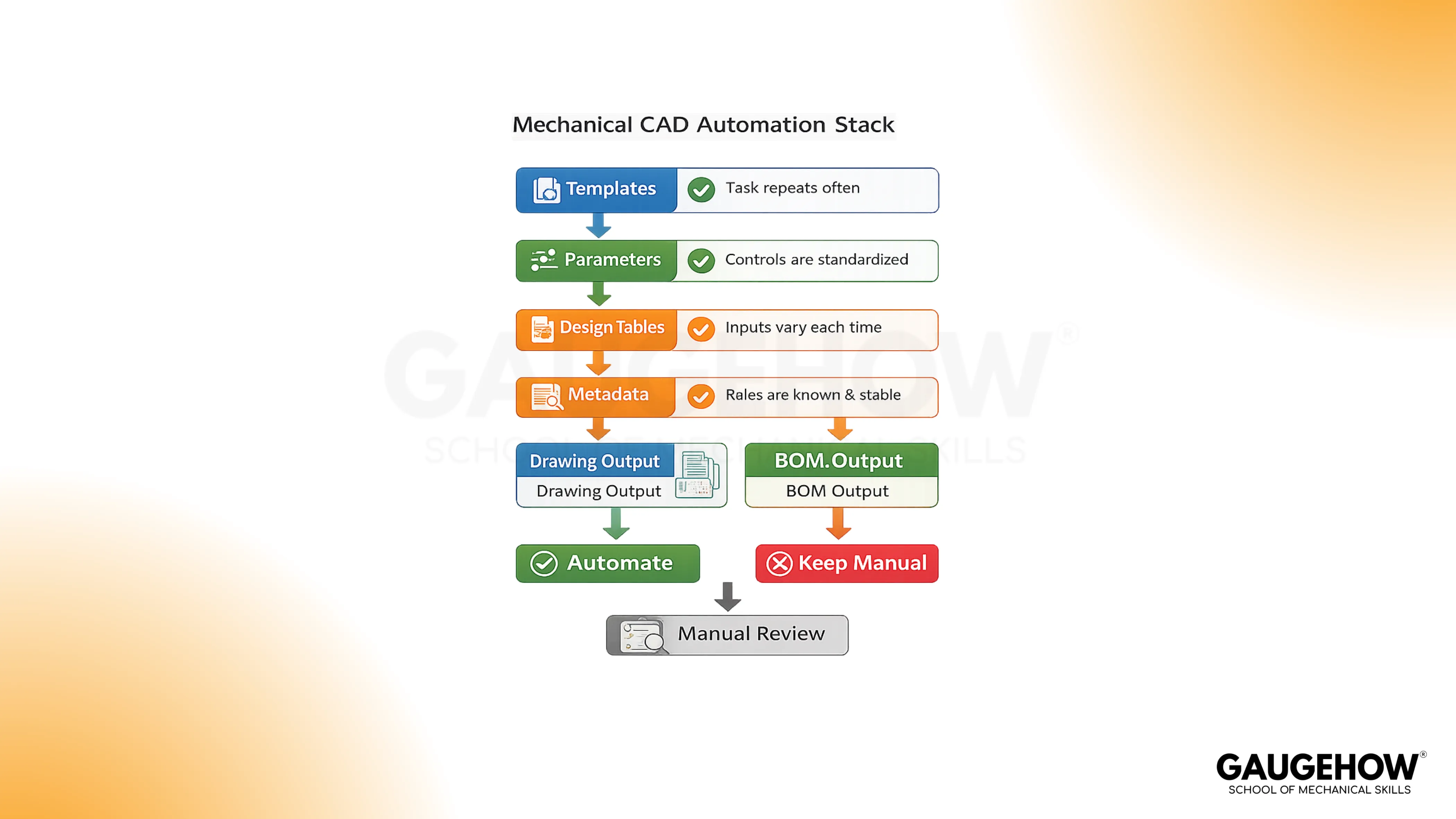
So when one enclosure width changes, the model updates, the hole pattern shifts, the sheet views refresh, and the item data stays aligned.
Ordinary CAD work still depends on manual editing. Generative design explores solutions. A simple macro clicks faster.
Rule-based design sits in a different place, because it controls what may change and what must stay fixed. That boundary keeps the workflow believable, and it also keeps the engineer accountable for the calls that still need review.
Where Manual CAD Work Slows Mechanical Teams
The slowdown usually starts in familiar places. Part families get rebuilt from old files. Sheet views and title blocks get edited again.
Quantities get typed by hand. Export packs get saved under mixed names. One late assembly change then spreads across several related files.
You still own the key decisions:
Define the allowed inputs and locked rules
Decide which outputs update together
Keep properties, names, and part data clean
Hold the review checks before files move forward
Keep final approval and exceptions with the engineer
A good first project is not the smartest workflow. It is the most repeatable one. You want work that happens often, follows one standard, and leaves a clear proof check after the update.
Role/Task | Output | Tools | Downstream Use | Proof Check |
Bracket family updates | Variant model and drawing | Parameters, templates | Faster revision work | Sizes, notes, and names stay aligned |
Enclosure configuration | Approved assembly variant | Rules, forms | Sales to engineering transfer | Invalid options stay blocked |
Drawing pack setup | Standard sheet output | Linked views, properties | Review and issue | Notes and fields stay correct |
Item data and export pack | BOM plus file set | Metadata, batch actions | Purchasing and vendor handoff | Revision and file names match |
7 CAD Automation Examples For Mechanical Engineers
Bracket Families For Size Variants
Bracket families are usually the cleanest place to start, because the shape stays familiar while a few values change inside an approved range.
Width, hole spacing, thickness, and material rules can all move through one parent model, so the engineer stops copying old parts and starts controlling one logic path.
The benefit is not only speed. The output becomes easier to trust because the model, sheet views, and part data stay tied together.
A weak sketch or loose naming habit will still create trouble, but the trouble becomes visible sooner.
Enclosure Configurators
Enclosures, guards, and cabinets often vary by width, height, panel layout, door count, and hardware choice.
hat work suits controlled configuration because the assembly structure stays similar while the options change. So the engineer can choose approved values and get one consistent assembly state instead of building each variant from memory.
Good enclosure logic also protects the team from invalid choices.
Wrong panel counts, bad hardware combinations, or missed clearance checks are easier to catch when the options are already framed inside one controlled setup.
Automated Drawing Generation From Approved Models
This works best when the sheet format, view logic, title block, and standard notes are already known.
The aim is not to remove drawing judgment.
The aim is to prepare a strong first sheet, so the engineer spends time on dimensions, tolerances, and context rather than on repeated setup work.
That boundary is important. A generated sheet can still carry a wrong field or a weak note. So the drawing becomes faster to prepare, but it still needs a real review before issue.
Automated BOM Generation From Assembly Metadata
Assemblies with clean properties are strong candidates here, because the item list should come from the assembly structure rather than from manual typing.
Quantities, purchased items, standard parts, and descriptions become more reliable when the data is attached to the source model.
The gain is not only fewer typing errors. Planning and purchasing also receive cleaner output.
Poor metadata will still break the chain, so this example only works when the property discipline is already in place.
CAD Customization For File Control
A lot of repeated effort hides in fields, filenames, title blocks, and export names rather than in geometry.
Good CAD customization removes that repeated input work, so one approved value can feed several file level outputs together. That keeps the handoff cleaner, and it also reduces naming confusion during issue and revision work.
Small changes are usually enough at first. Linked properties, simple forms, and light macros often solve more than people expect.
Bigger add-ins can wait until the file structure is already healthy.
Design Tables And Rule-Based Design
Standard fasteners, spacers, hole patterns, and shaft variants work well with tables and controlled option logic.
Use design tables when the approved combinations are already known. Use rule-based design when one valid choice should trigger another, such as hardware size changing with plate thickness or hole calls changing with part class.
The value here is selection discipline. You reduce invalid combinations, and you also stop relying on memory for repeat choices.
The engineer still checks fit, strength, and context, but the starting point becomes far cleaner.
Release Pack Output For PDF, STEP, And DXF
Many pages stop at the model, but real teams still lose time at the final file stage.
PDF, STEP, and DXF output often needs naming control, export order, revision checks, and folder discipline before the package is ready for manufacturing or vendor use.
That is why file output belongs inside the conversation. A clean bundle saves time, but more importantly, it reduces confusion at the last mile.
Weak naming rules will spread mistakes quickly, so the standard has to be set early.
How Parametric Modeling Keeps Logic Stable
Strong parametric modeling keeps the change path clean because the master dimensions sit in the right place and the feature order still makes sense after revision.
That is why the first real win is not scripting. The first real win is a model that survives change without losing intent.
Weak logic does the opposite. Copied geometry starts drifting, references become harder to trust, and the downstream sheet no longer reflects the true part state.
So before you automate more steps, you need stable sketches, readable equations, and clear parent-child behavior.
Where CAD Automation Helps Most
Good CAD automation removes repeated setup work, and it does that without hiding the engineering logic.
Templates give you a clean start. Linked properties reduce repeated typing. Light macros cut routine clicks.
Deeper CAD API work can come later, once the file structure and review path are already stable.
That order keeps the workflow practical. It also helps a junior engineer learn the system properly, because the logic stays visible. When the structure is healthy, deeper tooling adds control. When the structure is weak, deeper tooling only makes the confusion move faster.
How To Choose The First Pilot
Pick the first pilot with four filters, not with excitement:
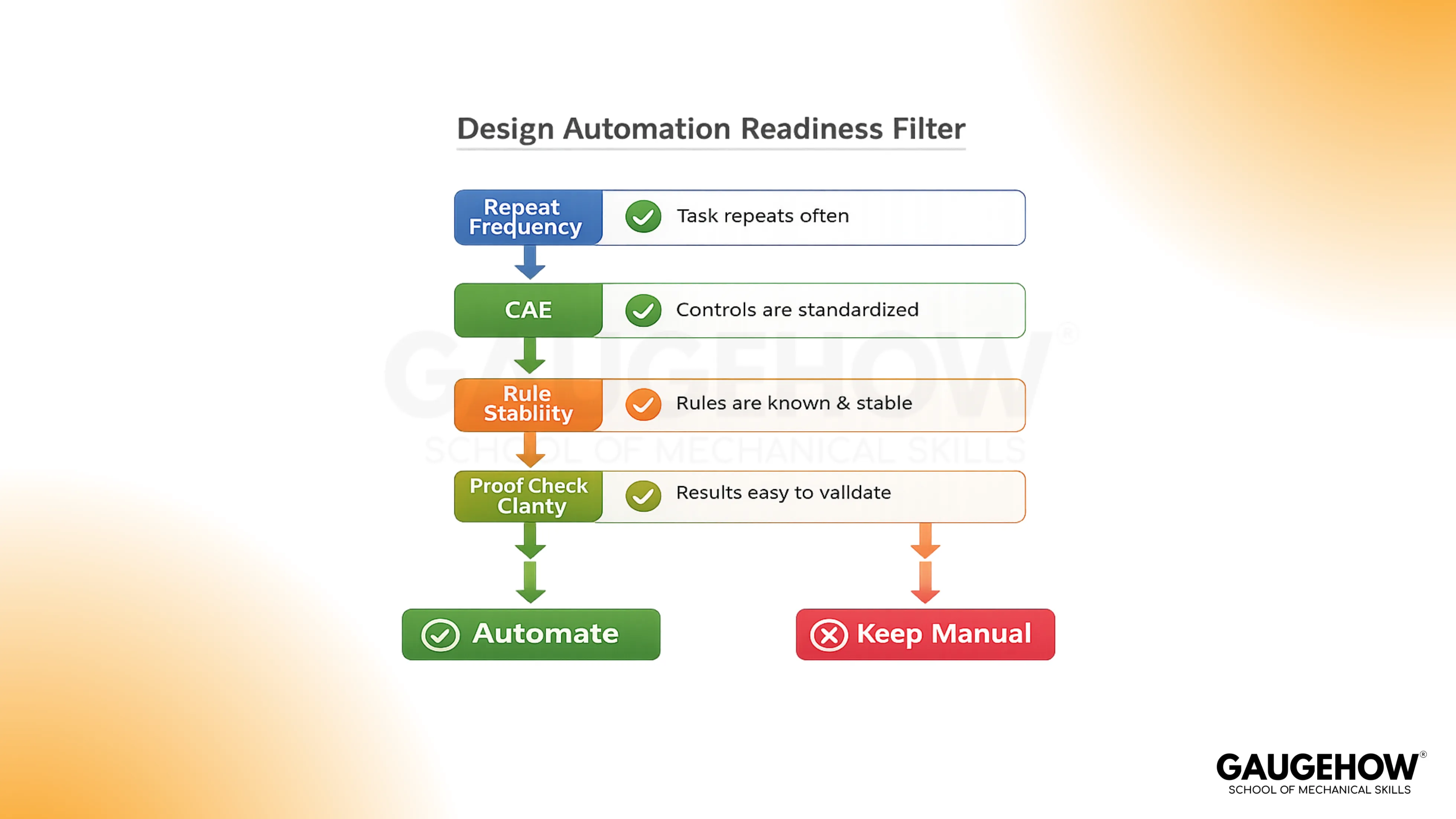
It often repeats in normal project work.
It already follows one fixed standard
It has low sensitivity before final review
It leaves a clear proof check after output
A bracket family usually fits. A standard enclosure often fits as well. A messy legacy assembly usually does not.
So the safest early win is the task you can explain clearly, test quickly, and review without debate.
Get Certified With Job-Focused Training
Software familiarity is not enough for professional work. You need guided practice on models, sheets, item data, and file control.
Gauge how courses are built for that, with expert-led project work and placement support.
Explore CAD Courses
Explore Mechanical Simulation Courses
You learn tools such as AutoCAD, SolidWorks, CATIA, Siemens NX, Fusion 360, ANSYS, and Python through practical engineering tasks.
Conclusion
Take one repeat bracket, enclosure, or sheet pack today and write four lines beside it: allowed inputs, fixed rules, required outputs, and review checks. Then treat design automation as disciplined engineering work, build one pilot you can prove, and move into GaugeHow training when you want guided project practice instead of random trial and error.
Frequently Asked Questions
Can Automated Drawing Generation Remove Drawing Review?
No. Automated drawing generation can prepare views, fields, and standard notes, but the engineer still checks dimensions, tolerances, context, and exceptions before the sheet is ready to issue.
Does Automated BOM Generation Fix Weak Metadata?
No. Automated BOM generation only works well when part properties, quantities, and purchased item rules are already clean. Bad metadata simply moves faster through the same chain.
Do Small Mechanical Teams Benefit From This Work?
Yes. Small teams often gain faster because repeated work is easier to spot. One clean bracket family or one reliable file pack can remove a surprising amount of repeated effort.
Does Every Workflow Need Coding First?
No. Many useful improvements begin with templates, linked fields, equations, and forms. Coding becomes useful later, once the logic is stable and the workflow needs deeper control.
What Should Stay Manual?
Final approval stays manual. Exception notes stay manual. Non-standard calls stay manual as well, because accountability still belongs with the engineer who signs off on the work.


